background image

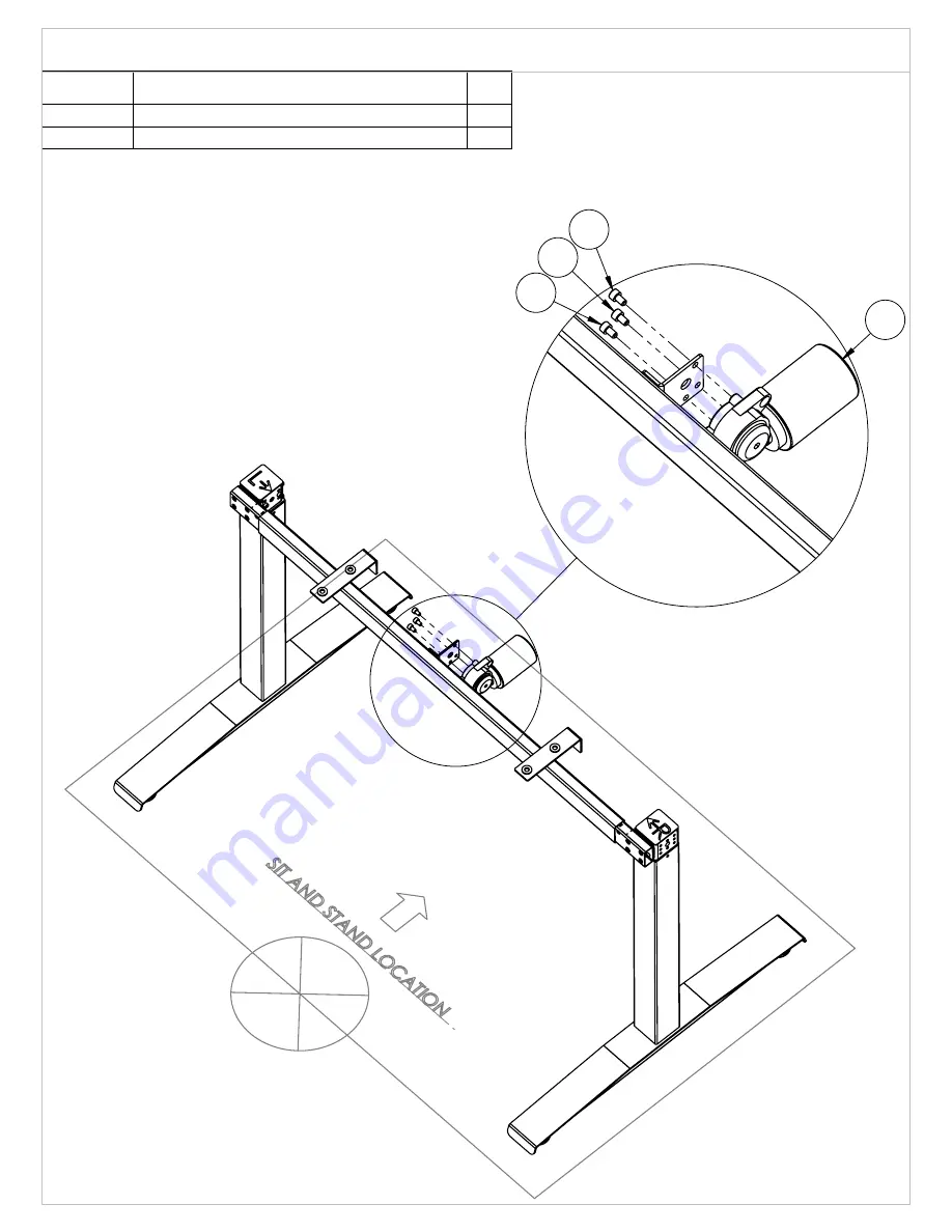
18

14

14

14

Pg.4/11

ITEM NO.

DESCRIPTION

QTY.

18

Motor TGM1-2252-002

1

14

Screw M6 XL10

3

Assembly Instruction:  Install Motor Assembly

Содержание ST SUPREME E23T

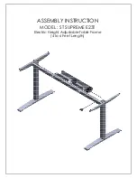
Страница 1: ...ASSEMBLY INSTRUCTION MODEL ST SUPREME E23T Electric Height Adjustable Table Frame 4 to 6 Feet Length...

Страница 2: ...01 Qty 1 Crossbar Motor Model CB 10 219 00 Qty 1 Cable Tray FA 00 220B 00 Qty 1 Right Column FA 20 106 ER 01 Qty 1 Foot FA 10 315 02 Qty 2 Crossbar Assy Left CB 10 217B 01 Qty 1 Screw M6XL10 Qty 3 Lev...

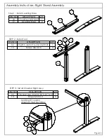
Страница 3: ...nstall Crossbar Left Assy Step 1 Install Leveling Base ITEM NO DESCRIPTION QTY 03 Foot FA 10 315 02 1 17 Leveling Base 2 ITEM NO DESCRIPTION QTY 01 Left Column FA 20 106 L 01 1 15 Screw M6 XL16 4 ITEM...

Страница 4: ...ll Crossbar Right Assy Step 1 Install Leveling Base ITEM NO DESCRIPTION QTY 03 Foot FA 10 315 02 1 17 Leveling Base 2 ITEM NO DESCRIPTION QTY 02 Right Column FA 20 106 ER 01 1 15 Screw M6 XL16 4 ITEM...

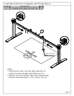
Страница 5: ...right direction to adjust the frame length fixed table top size 2 Tighten set screw M6 X4 after fixed frame length Recommanded length 115cm 145cm 175cm ITEM NO DESCRIPTION QTY 07 Crossbar Motor Model...

Страница 6: ...18 14 14 14 Pg 4 11 ITEM NO DESCRIPTION QTY 18 Motor TGM1 2252 002 1 14 Screw M6 XL10 3 Assembly Instruction Install Motor Assembly...

Страница 7: ...Left Stand Right Stand are at lowest position Please see attachment caution Refer Pg7 11 2 Tighten set screw M6 X4 after fixed frame length Pg 5 11 ITEM NO DESCRIPTION QTY 08 Axle Drive L390mm ET 00 3...

Страница 8: ...Left Stand Right Stand are at lowest position Please see attachment caution Refer Pg 7 11 2 Tighten set screw M6 X4 after fixed frame length Pg 6 11 ITEM NO DESCRIPTION QTY 8 Axle Drive L550mm ET 00...

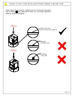
Страница 9: ...on The marking O not appear means it is at lowest position refer to below diagram Marking fully seen Marking partially seen Marking not seen Means at lowest position Press Press Pg 7 11 Caution Column...

Страница 10: ...06 06 13 13 13 13 Pg 8 11 ITEM NO DESCRIPTION QTY 06 Side L Plate FA 00 119 01 2 13 Screw M5 XL10 4 Assembly Instruction Install Side L Plate...

Страница 11: ...M5 Notes Step 1 Place Control Box to Cable Tray Step 2 Plug Motor connector and Handset connector to control box Pg 9 11 ITEM NO DESCRIPTION QTY 12 Cable Tray FA 00 220B 00 1 13 Screw M5 XL10 2 ITEM N...

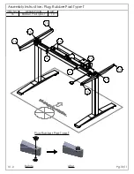
Страница 12: ...16 16 16 16 16 16 16 16 16 16 Plug Rubber Pad Type T Pg 10 11 Before V1 0 After ITEM NO DESCRIPTION QTY 16 Rubber Pad Type T 10 Assembly Instruction Plug Rubber Pad Type T...

Страница 13: ...n the desk moving down to lowest position After checking the signal motor constant reset was completed and ready to use 2 Any dismantle of electrical component follow below procedure Press both button...

Отзывы: