


installation, operation, and
maintenance instructions
page 7 of 12
Model AN--10K1
JARVIS
6244001:
®
PRODUCTS CORPORATION
33 ANDERSON ROAD, MIDDLETOWN, CONNECTICUT 06457--4926
UNITED STATES OF AMERICA E--MAIL.
TEL. 860--347--7271 FAX. 860--347--6978 WWW. j
arvisproducts.com
5.1 Make sure trigger lever (item 42) and trigger con-
tact bushing (item 1) move freely before the
stunner is connected to the air pressure line.
5.2 Connect quick connect socket (item 33) on stun-
ner to hose assembly (item 48).
OPERATION INSTRUCTIONS
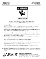
Eye and ear protection must be worn at all times while
operating the AN- 10K1 Pneumatic Stunner.
Note: Always disconnect quick connect socket (item
33) from
hose assembly
(item 48) when tool is not being
used.
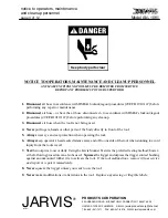
Operating air pressure must be maintained between a
minimum 150 psi (10.3 bar) and a maximum 175 psi
(12.1 bar).
Air pressure must never exceed 175 psi.
Installation of a safety valve on the air line will prevent
air pressure from exceeding the maximum pressure.
1
Connect air hose.
2
Each day
, before you begin operation, go through
the following check list:
2.1 Make sure that the compressed air supply is at the
proper pressure and that the lubricator is up to the
full mark.
Note: Keep body parts away from contact bushing
(item 1) when trigger is activated.
2.2 Make sure the tool is working correctly. Use
Jarvis
AST--100 Stunner Tester to insure pene-
trating shaft (item 27) is traveling at the proper
speed. As an alternative, the following proce-
dure can be used: Squeeze the trigger lever
(item 42) and displace the contact bushing (item
1) against an unmounted rubber tire.
If the tool
malfunctions, remove it from service and report
the problem to your supervisor immediately.
3 Use hanger bracket (item 62) to guide stunner to the
animal’s head.
Note: Operator’s head must be a safe distance away
and on one side of the stunner when the stunner is in
use to avoid any injury from tool’s recoil.
Keep hands away from the trigger contact bushing area
(item 1) when penetrating shaft (item 27) is activated.
4 Squeeze trigger lever (item 42).
5 Position the AN--10K1 stunner directly on the ani-
mal’s head to activate trigger contact bushing (item
1) and release penetrating shaft (item 27) .
6 After penetrating shaft (item 27) is released and ani-
mal is stunned, remove trigger contact bushing
(item 1) from the animal’s head.
7 Repeat procedure for next animal placed in stun-
ning box.
Note: If penetrating shaft (item 27) does not go back
automatically to its original position after animal is
stunned, the stunner must be fired again without being
in contact with the animal’s head.
Point stunner in a
safe direction, away from the animal and people.
Si-
multaneously squeeze trigger lever (item 42) and move
trigger firing shaft assembly (item 44) in direction of
main housing (item 13).
8 Disconnect quick connect socket (item 33) from
hose assembly (item 48) after stunning has been
completed.
MAINTENANCE INSTRUCTIONS
ALWAYS DISCONNECT THE AIR SUPPLY IN ACCOR-
DANCE WITH OSHA’S LOCKOUT/TAGOUT PROCE-
DURES (29 CFR 1910.147) BEFORE PERFORMING ANY
MAINTENANCE OR REPAIRS.
Refer to Figures A on pages 4 for referenced items.
Refer to Figure B, Trouble--shooting Chart, on page 10
for trouble--shooting procedures.
Always disconnect quick connect socket (item 33
)
from
hose assembly (item 48) before attempting any mainte-
nance or repairs.
Note: When testing stunner after completing mainte-
nance or repair procedures, operating air pressure can-
not be lower than 70 psi (4.8 bar).