


6 - 24
emPC-A/RPI3
(
Hardware and
Software Manual)
•
Programming Information
©
Janz Tec AG
Rev. 1.3
6
Programming Information
This chapter gives technical information on how to program, or adapt existing Linux drivers to the
emPC-A/RPI3 hardware and is intended for users familiar with creating own Linux kernels and drivers.
For standard Linux users, optionally our emPC-A/RPI3 driver package (chapter 5.2) is available and
this already includes all required drivers, therefore no driver programming is needed to use the emPC-
A/RPI3
hardware and it’s interfaces.
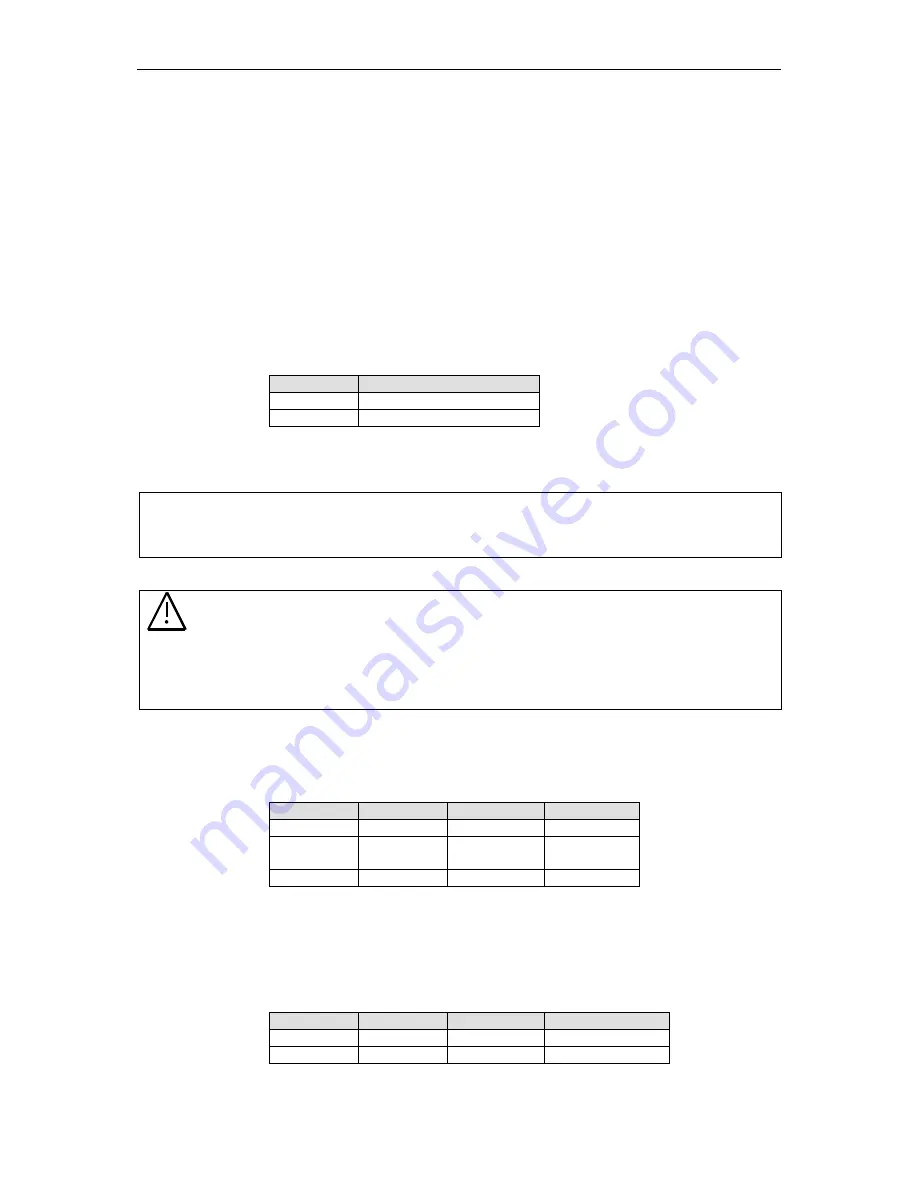
6.1 User LEDs
The two front panel LEDs of the CPU module are controllable by the user. They are controlled by
Raspberry GPIOs.
IO
GPIO
GREEN
GPIO5 (Pin 29)
RED
GPIO12 (Pin 32)
LEDs are turned on by setting the GPIO to low level.
Example:
root@raspberry ~$
echo "12" > /sys/class/gpio/export
root @raspberry ~$
echo "out" > /sys/class/gpio/gpio12/direction
root @raspberry ~$
echo "1" > /sys/class/gpio/gpio12/value
root @raspberry ~$
echo "0" > /sys/class/gpio/gpio12/value
NOTICE
When the emPC-A/RPI3 driver package (chapter 5.2) has been installed, the green LED
is configured to show the µSD-card activity. To control this LED by from the command
line, uncomment the entry
“dtparam=act_led_gpio=5” from the configuration file
/boot/config.txt and
remove all entries starting with “bcm2708.disk_*” from the
configuration file /boot/cmdline.txt and reboot the system and reboot the system. After
this, setting the output value of GPIO 5 controls the green LED.
6.2 I²C Bus
The emPC-A/RPI3 utilizes the Raspberry I2C bus to connect to several peripheral devices.
Type
Device
Address
Notes
EEPROM
-
0b1010000
Optional
Thermal
Sensor
DS75
0b1001000
Optional
RTC
MCP7940
0b1101111
Table 8: Internal I²C devices
6.3
SPI Bus
The emPC-A/RPI3 utilizes the Raspberry PI SPI bus to connector CAN and an additional UART.
Type
Device
Chip Select
Interrupt
CAN
MCP2515
CE0#
GPIO25 (Pin22)
UART
SC16IS740
CE1#
GPIO17 (Pin11)