background image

20

MC 9900

• 

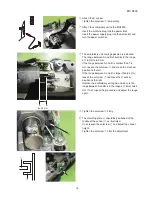
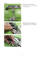
Attaching Guide bars to carriage unit

z

  Insert the guide bars 

q

 and 

w

 to the holes of 

X-carriage as shown.

q w

x

  Attach the guide bars to the carriage unit.

    Pull the guide bar 

q

 in the direction of arrow.

    Tighten the setscrews 

e

 and 

r

 temporarily.

e

r

Содержание MC12000

Страница 1: ...ACEMENT Y MOTOR REPLACEMENT PRINTED CIRCUIT BOARD S1 REPLACEMENT PRINTED CIRCUIT BOARD S2 REPLACEMENT EMBROIDERY UNIT DETECTING SWITCH REPLACEMENT FILM REPLACEMENT X SENSOR REPLACEMENT Y SENSOR REPLAC...

Страница 2: ...Removing Film guides 8 Removing Y carriage 8 9 Removing Y motor 10 11 Replacing Printed Circuti Board S1 12 Replacing Embroidery Unit Detecting Switch 12 Replacing Film 13 Replacing X sensor 14 15 Re...

Страница 3: ...fully extended position q x Remove the setscrew w c Slide the carriage in the direction of the arrow Remove the setscrew e v Remove the Y carriage cover upper e Preparation Remove Y carriage cover up...

Страница 4: ...3 MC 9900 b Remove the setscrews r 3 pcs r n Remove the X carriage cover unit m Remove the setscrews t 3 pcs t Removing X carriage cover and Embroidery unit cover t t t t...

Страница 5: ...e embroidery unit again Push down the carriage arm release lever q Retract the carriage arm to the stored position q 0 Move the carriage arm as far as it goes in the direction of arrow o 1 The rounded...

Страница 6: ...late 3 so the cable will not be damaged when moving 4 Move the carriage arm in the direction of arrow 4 5 Push down the carriage arm release lever q Extend the carriage arm To attach the Y carriage co...

Страница 7: ...brown e orange q and red w cords w q e Precision screwdriver x Remove the setscrews r to remove the X motor Attaching X motor Follow the above procedure in reverse Replacing Y motor Removing Y carriag...

Страница 8: ...7 MC 9900 c Remove the Y carriage cover lower Removing Film v Remove the setscrews e 2 pcs on the film holder e b Remove the film holder and the film...

Страница 9: ...s on the film guides m Remove the setscrews t 2 pcs on the film guides t t Removing Y carriage Pull the cable in the direction of arrow y to disconnect the flexible cable from the printed circuit boar...

Страница 10: ...i i 1 Remove the setscrew o 2 Remove setscrews 0 4 pcs see fig 1 on page 8 Remove the Y carriage o 0 3 Pull out the guide bars 1 and 2 from the Y carriage To attach the guide bars to the carriage foll...

Страница 11: ...Remove the guide bars X2 from the Y carriage Loosen the hexagonal socket screw 3 3 5 4 Slide the stopper 4 in the direction of arrow to access the setscrew 5 Remove the setscrew 5 5 Remove the setscr...

Страница 12: ...onnector 5 from the printed circuit board S2 4 9 Pry up the lock tab of the connector with a precision driver and pull out the red 6 orange 7 brown 8 brown 9 and red 0 cords Remove the Y motor Attachi...

Страница 13: ...connect the connectors from the printed circuit board S1 Remove the printed circuit board S1 To attach follow the above procedure in reverse Replacing Embroidery Unit Detecting Switch z Remove the set...

Страница 14: ...s on the film holder x Remove the film holder w and the film Attaching film c Replace the film Insert the film in the film cover v Insert the both edges of the film in the guides e then move the film...

Страница 15: ...crew r and t to remove the cord guide plates Remove the tube from the cord guide plate w q e Precision screwdriver e c Remove the setscrew y Remove the X sensor w q e Precision screwdriver Attaching X...

Страница 16: ...n and be sure the range between A and B is in the range of 7 8 mm to 8 2 mm If not repeat the procedure and adjust the range again n Attach the X sensor Tighten the setscrew r temporarily m Attach the...

Страница 17: ...the pulley under the X belt base plate v Hook the X belt to the pulley of X motor Adjust the X motor position and tighten the setscrews w 3 pcs temporarily Adjust the X belt deflection to about 3 mm...

Страница 18: ...r height so the shielding plate u should be positioned at the middle of the sensor i as illustrated Tighten the setscrew y to attach the Y sensor Insert the cords e r and t to the connector Plug the c...

Страница 19: ...Remove the Y belt Attaching Y belt b Attach the Y belt r n Be sure that the Y belt deflection to about 3 mm by pressing the middle of Y belt with approximately 30 grams of pressure If not turn the Y...

Страница 20: ...s in fully extended position x Turn the embroidery unit upside down Remove the cover w w c Move the Y carriage e under the hole r r e v Hook a slotted driver to the hole t To tighten the carriage move...

Страница 21: ...rs to carriage unit z Insert the guide bars q and w to the holes of X carriage as shown q w x Attach the guide bars to the carriage unit Pull the guide bar q in the direction of arrow Tighten the sets...

Страница 22: ...t X carriage moves on the guide bars smoothly Tighten the setscrews e r Tighten the setscrews t and y temporarily e r y t t y b Move the X carriage in the direction of arrows Tighten the setscrews t a...

Отзывы: