32
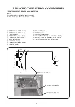
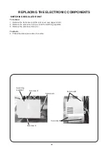
PRINTED CIRCUIT BOARD A
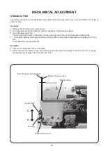
To remove:
1. Remove the front cover (see pages 6 to 7)
2. Pull out connectors from the printed circuit board A.
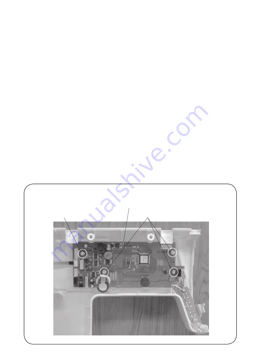
3. Remove the setscrews (4 pcs.) and the printed circuit board A.
To attach:
4. Follow the above procedures in reverse.
NOTE:
Do not disconnect the connectors by pulling on cord.
To disconnect, grasp the connector, not the cord.
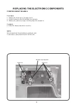
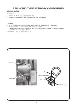
REPLACING THE ELECTRONIC COMPONENTS
Printed circuit board A
Setscrew
Setscrew


