J&W JW-A870T-UC3 Скачать руководство пользователя страница 40

-  -

 AMD Series                                                                                                   User's Manual 
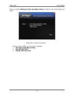
When you choose 

Mainboard Driver installation Utility

, the drivers menu should appear as 

below: 


                                         (This picture is only for reference)

        From the Drivers MENU you may make 4 selections:

        1. 

ATI Chipset Installation Utility 

        2. 

Onboard LAN Driver

        3. 

Realtek HD Audio Driver

Back <-         ATI Chipset Installation Utility

                       Onboard LAN Driver

                       Audio Driver


                                                                                     Exit

Содержание JW-A870T-UC3

Страница 1: ...User s Manual Socket AM3 Processor Mainboard JW A870T UC3 Rev 1 0 May 2010 Motherboard Website http www jwele com...

Страница 2: ...ot guarantee the accuracy of the contents This manual is purely technical documentation without any hint or other meanings and we won t commit users misunderstanding of the typesetting error Our produ...

Страница 3: ...MOS Memory Clearing Header 11 3 3 Keyboard Power Function 11 3 4 FAN Power Connectors 12 3 5 Front Panel Switches Indicators Headers 12 3 6 Additional USB Port Headers 13 3 7 Front Panel Audio 13 3 8...

Страница 4: ...duct Please check with the following list of accessories if there is any broken or missing part please contact your dealer or the local distributor SATA cables SATA power cables I O Shield User s manu...

Страница 5: ...ouse port 1 x S PDIF OUT port 1 x COM port 1 x RJ45 port 6 x USB 2 0 ports USB 1 1 is compliant 3 x Audio ports Line In Line Out MIC In Internal I O Connectors 1 x 24 pin ATX main power connector 1 x...

Страница 6: ...Mainboard Layout This picture is only for reference DIMM1 DIMM2 DIMM3 DIMM4 SFAN1 JBAT BT 1 SFAN2 PWR 12V OC BT _ OC SLC _ MINIPCIE JMINIPCIE JSPDIF ATXPWR AUDIO USB2 JRS890A01 D V1 0 205 295MM _ 3 S...

Страница 7: ...ports are used to connect USB 2 0 1 1 devices such as scanner speakers keyboard mouse hub digital camera joystick etc LAN The LAN port allows the motherboard to connect to a local area network by mea...

Страница 8: ...If the holes line up and there are screw holes you can attach the board with studs If the holes line up and there are only slots you can only attach with spacers Take the tip of the spacers and insert...

Страница 9: ...in accordance with the processor specifications It is not recommended that the system bus frequency be set beyond hardware specifications since it does not meet the required standards for the periphe...

Страница 10: ...DIMM modules of the same type and size on slots DIMM1 DIMM2 and another 2 DIMM modules of the same type and size on slots DIMM3 DIMM4 To install system memory 1 Power off the computer and unplug the A...

Страница 11: ...create a RAID 0 1 5 and 10 2 5 2 PCI and PCI Express slots Install PCI Express X16 graphics card into slot PCIE1 Install PCI Express X1 card into slot PCIE2 or PCIE3 Install mini PCI Express card into...

Страница 12: ...preset in the BIOS menu c you are unable to boot up the system because the CPU ratio clock was incorrectly set in the BIOS menu or d whenever there is modification on the CPU or memory modules This h...

Страница 13: ...D cable and the LED will light when the hard drive s is are being accessed RST Blue Reset Switch This connector connects to the case mounted reset switch which allows you to reboot without having to p...

Страница 14: ...ssignment 1 VCC 2 VCC 3 Data 0 4 Data 0 5 Data 0 6 Data 0 7 Ground 8 Ground 9 No Pin 10 NC 3 6 Additional USB Port Headers 3 7Front Panel Audio The headers conform to USB 2 0 1 1 specification Each US...

Страница 15: ...9 CPU downclocking 2 increase CPU voltage 8 decrease the CPU voltage 3 increase the memory voltage 7 decrease the memory voltage 4 increase the NB voltage 6 decrease the NB voltage 5 no function afte...

Страница 16: ...please plug the 20 pin ATX main power connector along with pin 1 and pin 13 PWR12V 12V Power connector Your power supply unit may come with a 4 pin or 8 pin 12V power connector The 12V power enables t...

Страница 17: ...ecial features on or off etc 3 Enhancing your computer s behavior For example speeding up performance by turning on shadowing or cache 4 2 To Run BIOS Setup First access BIOS setup menu by pressing F1...

Страница 18: ...mpletely match with what you see on your screen This chapter were based mainly on model JW A870T UC3 unless specif ically stated Do not change the BIOS parameters unless you fully understand its funct...

Страница 19: ...lors F5 Restore the previous CMOS value from CMOS only for Option Page Setup Menu F7 Discard Changes F8 Load Failsafe Defaults F9 Load Optimal Defaults F10 Save configuration changes and exit setup 4...

Страница 20: ...Select Item Change Option F1 General Help F10 Save and Exit ESC Exit Device Hard Disk Vendor ST380215AS Size 80 0GB LBA Mode Supported Block Mode 16Sectors PIO Mode 4 Async DMA MultiWord DMA 2 Ultra...

Страница 21: ...s or disables data multi sectors transfers When set to Auto the data transfer from and to the device occurs multiple sectors at a time if the device supports multi sector transfer frature When set to...

Страница 22: ...Table Disabled Enabled Enabled Enabled Enabled v02 61 C Copyright 1985 2006 American Megatrends Inc 4 5 4 Advanced setting GART Error Reporting This option should remain disabled for the normal opera...

Страница 23: ...nChip SATA Channel OnChip SATA Type OnChip IDE Type SATA IDE Combined Mode PATA Channel Config SATA ESP on PORT0 SATA ESP on PORT1 SATA ESP on PORT2 SATA ESP on PORT3 SATA ESP on PORT4 SATA ESP on POR...

Страница 24: ...the Secondary IDE Controller BOTH enables both IDE Controllers Select Screen Select Item Change Option F1 General Help F10 Save and Exit ESC Exit Onboard PCI IDE Controller Hard Disk Write Protect AT...

Страница 25: ...UTILITY Main USB Configuration Enables support for legacy USB AUTO option disables legacy support if no USB devices are connected Select Screen Select Item Change Option F1 General Help F10 Save and...

Страница 26: ...cy ISA devices Engineer mode Engineer mode control PCIPnP The PCIPnP menu items allow you to change the advanced settings for PCI PnP devices BIOS SETUP UTILITY Advanced Advanced PCI PnP Settings Clea...

Страница 27: ...to Enabled the system displays the message Press DEL to run Setup during POST Interrupt 19 Capture Allows option ROMs to trap interrupt 19 Press Esc key to return to Boot menu BIOS SETUP UTILITY Main...

Страница 28: ...drives Removable Drives Click Enter key to enter its submenu it will be display specifies the boot device priority sequence from available removable drives BIOS SETUP UTILITY Boot Boot Device Priorty...

Страница 29: ...to reset all previously set options Boot Sector Virus Protection Uses this option may prevent the change hard disk boot sector district table thus prevents the infection computer virus BIOS Write Pro...

Страница 30: ...guration and Power Interface ACPI support in the Advanced Programmable Interrupt Controller APIC When set to Enabled the ACPI APIC table pointer is included in the RSDT pointer list Optional Enabled D...

Страница 31: ...t Power on By RTC Alarm Allows you to enable or disable RTC to generate a wake event When this item is set to Enable the items RTC Alarm Date Days RTC Alarm Time will become user0configurable with set...

Страница 32: ...including System temperature CPU temperature FAN speed and all kinds of voltages BIOS SETUP UTILITY Power PC Health Fan configuration mode setting Select Screen Select Item Change Option F1 General He...

Страница 33: ...age Control Auto v02 61 C Copyright 1985 2006 American Megatrends Inc BIOS SETUP UTILITY JustW00t Overclocking Configuration The HyperTransport link will run at this width Select Screen Select Item En...

Страница 34: ...the DRAM scrub rate so all of memory is scrubbed in 8 hours Select Screen Select Item Change Option F1 General Help F10 Save and Exit ESC Exit ECC Mode DRAM ECC Enable DRAM SCRUB REDIRECT 4 Bit ECC MO...

Страница 35: ...MemClk Tri Stating during C3 and Alt VID Memory Hole Remapping Enables or disables the memory remapping around the memory hole DCT Unganged Mode This item allows the selection of the unganged DRAM mo...

Страница 36: ...es and exit setup Ok Cancel Ok BIOS SETUP UTILITY Main Advanced Boot Security Power JustW00t Exit Exit Options Exit system setup after saving the changes F10 key can be used for this operation Select...

Страница 37: ...Exit Discard Changes Load Optimal Defaults Load Failsafe Defaults v02 61 C Copyright 1985 2006 American Megatrends Inc Discard changes and exit setup Ok Cancel Ok BIOS SETUP UTILITY Main Advanced Boo...

Страница 38: ...on opens a dialog box that let you install optimized defaults for all appropriate items in the Setup Utility Select OK and then Enter to install the defaults select Cancel and then Enter to not instal...

Страница 39: ...elow If the menu does not appear double click My Computer double click CD ROM drive or click Start click Run type X AUTORUN EXE assuming X is your CD ROM drive This picture is only for reference From...

Страница 40: ...y the drivers menu should appear as below This picture is only for reference From the Drivers MENU you may make 4 selections 1 ATI Chipset Installation Utility 2 Onboard LAN Driver 3 Realtek HD Audio...

Отзывы: