background image

-  -

  ATI 690 Series                                                                                               User Manual

2.3 Installation of the CPU and CPU Cooler

    Before installing the CPU, please comply with the following conditions:

    1. Please make sure that the mainboard supports the CPU.

    2. Please take note of the one indented corner of the CPU. If you install the CPU in the wrong     

       direction, the CPU will not insert properly. If this occurs, please change the insert direction      

       of the CPU.

    3. Please add an even layer of heat sink paste between the CPU and CPU cooler.

    4. Please make sure the CPU cooler is installed on the CPU prior to system use, otherwise 

        overheating and permanent damage of the CPU may occur.

    5. Please set the CPU host frequency in accordance with the processor specifications. It is not 

        recommended that the system bus frequency be set beyond hardware specifications since 

        it does not meet the required standards for the peripherals. If you wish to set the frequen-     

        cy beyond the proper specifications, please do so according to your hardware     

        specifications including the CPU, graphics card, memory, hard drive, etc.


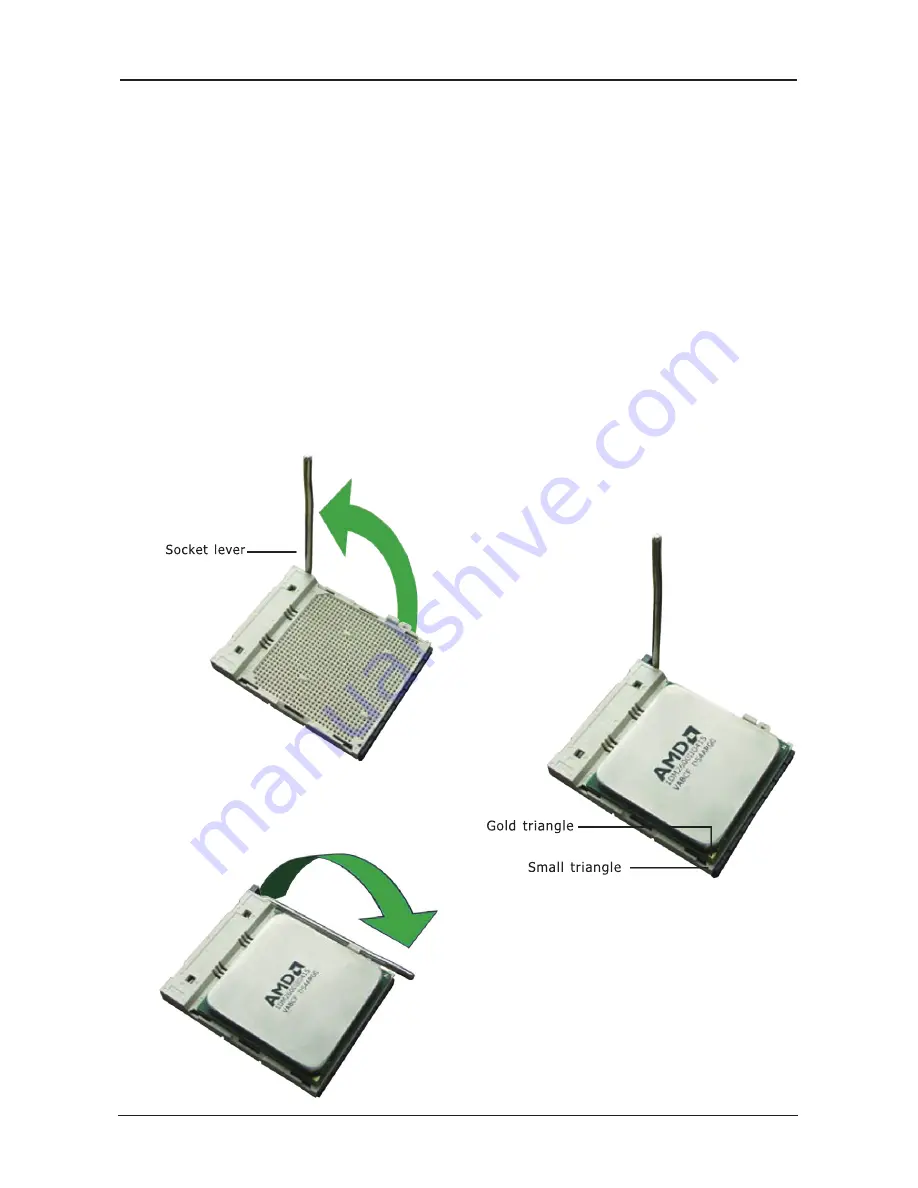
2.3.1 Installation of the CPU

1. Unlock the socket by pressing the 

   lever sideways, then lift it up to a 90

o

.

2. Position the CPU above the socket such 

    that the CPU corner with the gold 

    triangle matches the socket corner with 

    a small triangle.

3. Carefully insert the CPU into the socket 

    until it fits place.

4. When the CPU is in place, push down 

   the socket lever to secure the CPU. 

   The lever clicks on the side tab to 

   indicate that it is locked.

Figure 1

Figure 3

Figure 2

Содержание ATI 690 Series

Страница 1: ...User Manual ATI 690 Series ATI 690G 690C Socket AM2 Processor Mainboard Rev 1 00 Aug 2007 P N 80ENATI690 Website http www jwele com The Possible Of Impossible...

Страница 2: ...not guarantee the accuracy of the contents This manual is purely technical documentation without any hint or other meanings and we won t commit users misunderstanding of the typesetting error Our prod...

Страница 3: ...Panel Switches Indicators Headers 12 3 6 Additional USB Port Headers 13 3 7 Serial Port Headers 13 3 8 IR Connection Headers 13 3 9 Front Panel Audio Connection Header 14 3 10 Internal Audio Connector...

Страница 4: ...cking and accessories if there is any broken or part missing please contact with your franchiser HDD Cable X 1 Serial ATA Cable X 1 Rear I O Panel X 1 User s Manual X 1 Driver Utility CD X 1 FDD Cable...

Страница 5: ...Power Management ACPI CPU temperature Fan speed System Voltage monitoring Integrate Ports 1 x PS 2 Keyboard port 1 x PS 2 Mouse port 1 x VGA port 1 x DVI port optional for RS690G chipset only 1 x RJ4...

Страница 6: ...ATI 690 Series User Manual 1 3 Mainboard Layout This picture is only for reference...

Страница 7: ...digital camera joystick etc AUDIO1 Cen Sub Center Subwoofer Connect to the center and subwoofer channel in the 7 1 channel audio system R L R R Rear Left Rear Right Connect to the rear left and rear r...

Страница 8: ...ine up the holes on the board with the mounting holes on the chassis If the holes line up and there are screw holes you can attach the board with studs If the holes line up and there are only slots yo...

Страница 9: ...y in accordance with the processor specifications It is not recommended that the system bus frequency be set beyond hardware specifications since it does not meet the required standards for the periph...

Страница 10: ...DDRII3 and another 2 DIMM modules of the same type and size on slots DDRII2 DDRII4 DDRII1 and DDRII3 slots are made of the same color DDRII2 and DDRII4 are made of another same color To install syste...

Страница 11: ...ess X16 graphics card into slot PCIE1 Install PCI card into slots PCI1 or PCI2 Each of the IDE port connects up to two IDE drives at Ultra ATA 66 100 133 mode by one 40 pin 80 conductor and 3 connecto...

Страница 12: ...never there is modification on the CPU or memory modules This header uses a jumper cap to clear the CMOS memory and have it reconfigured to the default values stored in BIOS Pins 1 and 2 shorted Defau...

Страница 13: ...eset Control This connector connects to the case mounted reset switch for rebooting your computer without having to turn off your power switch This is a preferred method of rebooting in order to prolo...

Страница 14: ...t Header This COM1 header supports a serial port module Pin Pin Assignment Pin Pin Assignment 1 VCC 2 VCC 3 Data 0 4 Data 1 5 Data 0 6 Data 1 7 Ground 8 Ground 10 NC FUSB1 FUSB2 1 2 9 10 Pin Pin Assig...

Страница 15: ...io Pin No Definition 1 MIC 2 GND 3 MIC Power 4 NC 5 Line Out R 6 NC 7 NC 8 No Pin 9 Line Out L 10 NC F AUDIO _ 1 2 9 10 1 3 9 Front Panel Audio Connection Header This header provides the connection to...

Страница 16: ...connector 3 11 ATX Power Input Connectors This mainboard provides two power connectors to connect power supplier Pin No Definition 1 CD L 2 GND 3 GND 4 CD R GND GND 12V 12V 1 2 3 4 3 3V 12V 12V 5VSB...

Страница 17: ...the system time or date or turning special features on or off etc 3 Enhancing your computer s behavior For example speeding up performance by turning on shadowing or cache 4 2 To Run BIOS Setup First...

Страница 18: ...n these two methods should be fail that you restart the system by powering it off and then back on After pressing Del key the main menu screen appears Press DEL to enter SETUP Standard CMOS Features T...

Страница 19: ...ve CMOS value settings to CMOS and exit setup Exit Without Saving Abandon all CMOS value changes and exit setup 4 5 2 Control Keys Press F1 to pop up a small help window that describes the appropriate...

Страница 20: ...lp Menu Level To auto detect the HDD s size head on this channel Move Enter Select PU PD Value F10 Save ESC Exit F1 General Help F5 Previous Values F6 Fail Safe Defaults F7 Optimized Defaults Press En...

Страница 21: ...This item displays the number of cylinders at which to change the write timing Landing Zone This item displays the number of cylinders specified as the landing zone for the read write heads Sector Th...

Страница 22: ...ter key you can enter its submenu where the hard disks detected can be selected for the booting sequence to boot up system Virus Warning Allow you to choose the VIRUS Warning feature for IDE Hard Disk...

Страница 23: ...forget the password you will have to open the computer case and clear all information in the CMOS before you can start up the system But by doing this you will have to reset all previously set option...

Страница 24: ...ral Help F5 Previous Values F6 Fail Safe Defaults F7 Optimized Defaults LDT PCI Bus Control Click Enter key to enter its submenu Phoenix Award WorkstationBIOS CMOS Setup Utility LDT PCI Bus Control LD...

Страница 25: ...t you to keep the default PCIE Common Clock We suggest you to keep the default GFX0 Slot Power Limit Watt We suggest you to keep the default GPP Slot Power Limit Watt We suggest you to keep the defaul...

Страница 26: ...F6 Fail Safe Defaults F7 Optimized Defaults Onboard Device Click Enter key to enter its submenu Phoenix Award WorkstationBIOS CMOS Setup Utility Onboard Devices Onboard PCIE SIL3132 SATA Onboard SIL3...

Страница 27: ...s UltraDMA change the appropriate item on this list to Auto You may have to install the UltraDMA driver supplied with this mainboard in order to use an UltraDMA device Back to Integrated Peripherals S...

Страница 28: ...ay you want your system to power on Password Use a password to power on the system select this option then press Enter Enter your password You can enter up to 5 characters Type in exactly the same pas...

Страница 29: ...ser Define DPMS Support Disabled Disabled Instand Off Disabled Disabled Disabled 0 0 0 0 Item Help Menu Level Move Enter Select PU PD Value F10 Save ESC Exit F1 General Help F5 Previous Values F6 Fail...

Страница 30: ...ou can set this field to Disabled The IRQ previously occupied by the VGA card will be available for your new device Phoenix Award WorkstationBIOS CMOS Setup Utility PnP PCI Configurations Reset Config...

Страница 31: ...ensor Show On Post Disabled 28o C 82o F 30o C 86o F 0 RPM 3096 RPM 1 33 V 1 88 V 1 21 V 1 24 V 3 36 V 5 16 V 3 21 V 5 15 V Disabled 5 Disabled Item Help Menu Level Move Enter Select PU PD Value F10 Sa...

Страница 32: ...ss Enter Press Enter Press Enter Auto Auto Enabled 200MHz Item Help Menu Level Move Enter Select PU PD Value F10 Save ESC Exit F1 General Help F5 Previous Values F6 Fail Safe Defaults F7 Optimized Def...

Страница 33: ...e Setup Utility Press Y and then Enter to install the defaults Press N and then Enter to not install the defaults The optimized defaults place demand on the system that may be greater than the perform...

Страница 34: ...continue 4 5 14 Save Exit Setup Highlight this item and press Enter to save the changes that you have made in the Setup Utility and exit the Setup Utility When the Save and Exit dialog box appears pre...

Страница 35: ...below If the menu does not appear double click My Computer double click CD ROM drive or click Start click Run type X AUTORUN EXE assuming X is your CD ROM drive This picture is only for reference From...

Страница 36: ...lity the drivers menu should appear as below This picture is only for reference From the Drivers MENU you may make 3 selections 1 ATI Chipset All IN ONE Installation Utility 2 LAN Driver 3 Audio Drive...

Отзывы: