background image

13

 Installing the Highway Light Kit and Wiring Harnesses

1.  Insert the main wiring harness starting with the end opposite the7-prong connector, through the grommet located at the front of 

the gooseneck of the header transport main frame and exit the A-frame behind the gooseneck.

2.  Extend the main wiring harness along the inside right side of the header transport main frame. Reinsert the main wiring harness 

through the grommet located along the front of the A-frame and extend the harness through the main frame tubing toward the rear 

of the transport. 

If equipped with brakes:

3.  Insert one brake harness extension through the right side grommet located behind the goose-neck and extend the wires 

toward the rear of the main frame. 

4.  Insert the other brake harness through the left side grommet located behind the goose-neck and extend the wires toward 

the rear of the main frame.

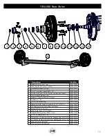
5.  Run one brake harness through the grommets on the main frame base adjacent to the rear axle. Connect one end of the 

brake harness into the first wheel electric brake unit. Connect the brake harness extension into the second end of the main 

harness. Connect the other end of the brake harness extension into the second wheel electric brake unit and connect the 

other end to the main harness.

6.  Run the main wiring harness out the grommet located behind the rear axles.

7.  Secure the 2-to-1 harness extension to the inside face of the rear main frame using two self-tapping screws. Connect the end of the 

main wiring Harness to the corresponding connector end of the 2-to-1 harness extension.

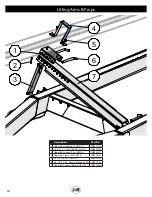
8.  Place the extension bracket at the rear end of the upper bar. Attach using the two angle iron supports and secure with four 1/2” x 7” 

bolts, washers and nuts.

9.  Place the light mounting bracket at the end of the exension bracket arm so the light mounting bracket is level or horizontal and 

extends toward the center of the header transport. Secure using two 1/2” x 1-1/4” Gr5 flange bolts and flange nuts.

10.  Slide the extendable portion of the telescoping arm into the light mounting bracket and tighten the handle nut until the bracket is 

secure. Extend the arm until the light assembly is within 16” of the outer extremity of the unit.

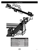
11.  Mount one light assembly at the end of the light mounting bracket (L/H light) and another assembly at the end of the telescoping 

arm (R/H light). Secure each light assembly using four self-tapping screws. Each light assembly should be mounted so the single 

amber light is positioned toward the outside of the header, and the amber and red lights are facing rearward.

12.  Secure the SMV emblem to the light mounting bracket using two 1/4” x 1” bolts and lock nuts. Ensure the SMV emblem remains 

visible from the rear during highway transport.

13.  Place one amber reflective decal at the outward and front side of both the telescoping arm and light mounting bracket. Place one 

red and orange Reflective Decal on the rearward end of the telescoping arm and light mounting Bracket. Place the red reflective 

decal directly above the orange decal.

14.  The main wiring harness should already be installed in the main frame base and connected to the 2-to-1 harness extension attached 

to the rear of the main frame base. Connect each light to the 2-to-1 harness extension using the light wiring harness. Using the 

enclosed self-tapping screws, secure the wire cover over the light wire harness along the upper bar. 

If equipped with brakes:

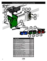
15.  Secure the break away kit and bracket to the front, right side of the main frame. Secure the break away switch to the top of 

the gooseneck. Run the black and blue wires through the adjacent grommet and extend to the rear of the gooseneck.

16.  Using a self-tapping screw, attach the white wires from the break away kit and the main wiring harness to the main frame.

17.  Connect the blue wire from the break away kit to the blue wire on the break away switch. Connect the black wire on the break 

away kit to the black wire on the main wiring harness. Connect the black wire on the break away switch to the light blue wire 

on the main wiring harness.

Set-Up Instructions

Содержание Trail-Blazer TB-6000

Страница 1: ...road Street P O Box 547 Fort Recovery OH 45846 Ph 419 375 2376 Fax 419 375 2708 www jm inc com Rev 1 12 2021 Trail Blazer H E A D E R T R A N S P O R T Operator s Manual TB 8000 Trail Blazer Heavy Dut...

Страница 2: ......

Страница 3: ...Instructions 15 Standard Dolly 16 Torsion Dolly 17 TB 6000 Rear Axles 18 TB 8000 Rear Axles 19 7k Idler Hub 20 Header Mounts and Tie Down Assembly 21 Rear Upper Bar Support 22 Lifting Arms Props 23 Up...

Страница 4: ...sufficient maintenance or iv normal wear or tear This warranty does not cover products that are previously owned and extends solely to the original purchaser of the product Should the original purchas...

Страница 5: ...ns that will help you achieve years of dependable performance and help maintain safe operating conditions If this machine is used by an employee or is loaned or rented make certain that the operator s...

Страница 6: ...should be such that complete control and machine stability is maintained at all times 7 Where possible avoid operating near ditches embankments and holes Reduce speed when turning crossing slopes and...

Страница 7: ...ter Spindle Size Back 4 2 1 2 Diameter Wheel Size 16 x 6 8 Bolt Tire Size 235 85R16F Steel Upper Bar 4 x 8 x 3 16 Steel Tubing Upper Bar Length 32 38 42 or 48 Arched Main Frame 4 x 8 x 1 4 Tubing Rear...

Страница 8: ...t Failure Decal JM0014996 3 Warning Fasten Header Securely To Transport Before Moving Decal JM0039381 4 J M Oval Decal Small 3 5 8 x 5 1 4 JM0015150 5 TB 6000 Decal JM0040063 6 Warning Always Use Safe...

Страница 9: ...16 400 ft lbs 20mm 475 ft lbs 22mm 640 ft lbs Always tighten hardware to these values unless a different torque or tightening procedure is listed for specific application Fasteners must always be repl...

Страница 10: ...uctions Maintenance Adjust the brackets on the header transport to best fit your make and model header Note When mounting the header NEVER position yourself under or near the header Securely fasten th...

Страница 11: ...d on the wrong side of the transport and the other rail should be used Align the holes in the support rail with the rear axles and loosely secure to each axle using a 3 8 x 3 1 2 x 3 1 2 UBolt 2 3 8 f...

Страница 12: ...e channel arms using 2 5 8 x 6 pins and hair pins Be sure to position all three slide brackets at the same position on the channel arm Position the upper bar on top of the three slide brackets and sec...

Страница 13: ...flange bolts and flange nuts 10 Slide the extendable portion of the telescoping arm into the light mounting bracket and tighten the handle nut until the bracket is secure Extend the arm until the lig...

Страница 14: ...transport place the decals on base unit main frame and at the back of the unit on the upper bar as shown below Placing the Amber Red and Orange Reflective Decals Ag Version Place the decals on the ma...

Страница 15: ...ension Stop Spacer for 1 1 4 Bolt JM0027776 6 7 8 9 x 2 1 4 Gr5 Z Hex Bolt JM0016685 7 2 1 4 Double Ended Spindle Trail Blazer Dolly JM0030465 8 Compression Spring 1 x 1 3 4 for Door Assembly Tongue L...

Страница 16: ...ion Flex Outer Tongue JM0028770 5 Torsion Flex Trail Blazer Inner Tongue Ball Hitch JM0028697 6 Compression Spring 1 x 1 3 4 for Door Assembly Tongue Latch JM0001688 7 Spacer Blocks 2 1 2 6 15 Ton SB...

Страница 17: ...2k 7k Axles JM0035955 6 D Washer 1 ID JM0039578 7 14125A Roller Bearing JM0039542 8 Bearing Cup for Superior Gearbox 14 20 414276 JM0025077 9 7K Hub Drum with Studs Nuts and Races JM0041461 10 Stud 9...

Страница 18: ...JM0039578 7 14125A Roller Bearing JM0039542 8 Bearing Cup for Superior Gearbox 14 20 414276 JM0025077 9 7K Hub Drum with Studs Nuts and Races JM0041461 10 Stud 9 16 18 x 2 13 16 JM0020625 11 Cup Larg...

Страница 19: ...39542 4 1 USS Flat Washer JM0003063 5 1 14 Gr2 Z Castle Hex Nut JM0002139 6 Cotter Pin for 1 x 3 2 5 Clevis Pin JM0003064 7 Grease Cap Solid for 7k Idler Hub JM0058750 8 Cup Large Inner 12 Ton 25520 J...

Страница 20: ...03076 7 1 2 13 Gr2 Z Centerlock Hex Nut JM0001511 8 Tie Down Bracket 4 x 8 JM0058789 9 1 2 13 x 5 1 2 Gr5 Z Hex Bolt JM0001498 10 2 Tie Down Ratchet 10 000 lb RA 1 JM0003084 11 5 8 USS Flat Washer JM0...

Страница 21: ...Z Hex Bolt JM0009914 5 Splice Clamp for 48 Top Tube JM0012934 6 1 2 13 Gr2 Z Centerlock Hex Nut JM0001511 7 Knee Brace Clamp Lower Weldment JM0030417 8 Cotter Pin for 1 x 3 2 5 Clevis Pin JM0003064 9...

Страница 22: ...Mount UBSM 3 JM0015133 2 3 16 x 2 1 2 Hair Clip Pin 316HP JM0001657 3 Upper Bar Support Arm UBSA 3 JM0003077 4 Upper Bar Clamp 4x8 UBC 3 JM0003081 5 1 2 13 Gr5 Z SF Hex Nut JM0002153 6 3 4 x 8 Z L Pi...

Страница 23: ...8 9 Description Part No 1 1 4 x 1 Self Tapping Screw JM0001716 2 Breakaway Switch with Cable BAS 1 JM0001843 3 Wire Harness Storage Bracket WHB 1 JM0001438 4 Trail Blazer Front Fender JM0010085 5 1 4...

Страница 24: ...ex Nut JM0002152 7 3 8 16 x 1 Gr5 Z SF Hex Bolt JM0002092 8 3 8 Rubber Metal Flat Washer JM0030416 9 1 2 13 x 3 1 2 Gr5 Z Hex Bolt JM0009914 10 1 2 ID 1 3 8 OD Z Flat Washer JM0003082 11 Header Transp...

Страница 25: ...0001440 3 1 2 13 x 7 Gr5 Hex Bolt JM0001595 4 Header Transport Light Mount Extension Bracket EB 1 JM0001393 5 1 2 13 x 1 1 2 Gr5 Z Hex Bolt JM0002100 6 Neoprene Vibration Damping Mount with 5 8 Diamet...

Страница 26: ...der Transport Highway Light Bar Weldment LMB 2 JM0030217 2 1 ID x 3 16 GW x 1 3 16 GD Grommet JM0016784 3 M6 1 0 x 25 Gr5 YZ Carriage Bolt JM0019445 4 M6 Flat Washer JM0019447 5 M6 1 0 YZ SF Hex Nut J...

Страница 27: ...5 Z Bent L Bolt JM0021419 3 Header Transport Light Mounting Bracket LMB 1 JM0001374 4 Slow Moving Vehicle Sign Bracket JM0001645 5 Slow Moving Vehicle Sign JM0001616 6 1 4 x 1 1 2 Self Tapping Screw J...

Страница 28: ...nsport Left Side LED Light Assembly JM0001680 3 Trail Blazer Rear Light Harness Ag JM0030481 4 Breakaway Switch with Cable BAS 1 JM0001843 5 Break Away Battery Box Assembly HSBB1 JM0001833 6 Header Tr...

Страница 29: ...Harness Ag JM0030481 4 Header Transport Harness 2 to 1 Extension JM0050904 5 Trail Blazer Brake Harness Extension Black and White JM0030437 6 Trail Blazer Rear Light Harness Extension Brown Green Yell...

Страница 30: ...tangular Cart HS Box JM0018837 5 Trail Blazer Rear Light Harness Extension Brown Green Yellow and White JM0030439 6 Side Marker Light Main Frame Yellow SML 2 JM0030426 7 Trail Blazer Side Light Wire S...

Отзывы: