


27
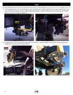
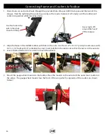
5. Mount the 4’ x 8” hydraulic cylinders under the toolbar frame as shown below. Secure the cylinders with 1” x
3-3/8” pins.
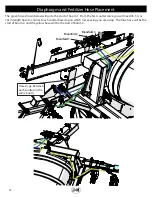
6. Connect the hoses from the top two ports of the valve bank on the main frame to the 4” x 8” hydraulic lift
cylinders. These hoses will be labeled in yellow.
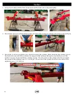
7. Connect the hoses from the bottom two ports of the valve bank on the main frame to the 4” x 24” hydraulic
fold cylinders. These hoses will be labeled in red.
8. Set down pressure gauge at 650psi and test hydraulic functions.
Connecting Frame and Coulters to Toolbar
Содержание Nitro Gro 5010
Страница 2: ...2 1 2 3 4 5 7 9 10 11 12 13 14 15 16 17 18 19 20 2 1 8 7 21 22 23 24 25 26 27 2 6 Decals...
Страница 18: ...18 This page intentionally left blank...
Страница 33: ...33...


