Issue: 01.05.2019
Page 8
Commissioning
•
Check compressor suction superheat. This should be
between 10K and 20K at normal operating conditions.
•
Final adjustment of safety switch settings and fan speed
control.
•
Allow the system to run for 3 – 4 hours. Check compressor
oil level and top up with the correct oil type as required
(see page 3). Recheck the compressor oil level again after
24 hours operation.
•
Carry out final leak test and ensure all panels/covers are
fitted and screws tightened.
•
Log all information along with the system model and serial
numbers for future reference.
•
Ensure that the customer / responsible person are
provided with basic operating instructions and where
electrical isolators are situated in case of emergency.
Compressor operation
Scroll compressor motors are designed to run only in one direction.
This is not an issue with single phase compressors as they will always
run in the correct direction. The correct rotation of a three phase
compressor motor depends on the connection of the three
incoming phases to the unit. Correct rotation can be determined by
a drop in suction pressure and a rise in discharge pressure when the
compressor is energized. Running the compressor for a short period
of time in reverse direction will have no negative impact but
prolonged running in reverse direction may cause premature
failure.
To reverse the rotation of a three phase scroll compressor,
shut off the incoming power supply to the unit, swap connection of
any two of the three incoming phases at the unit isolator, reapply
power to the unit and following compressor restart, recheck
operating pressures.
Compressor rotalock connections
The rotalock connections as used on some compressor models are
sealed with Loctite 554 thread sealant. The connections should be
leak tested at commissioning and during service/maintenance
visits. For further information including recommended torque
tightening values, please refer to Service & Maintenance section
on pages 21-22.
Vacuum operation
Do not operate scroll compressors in a vacuum condition, as this
will cause the scrolls to overheat very quickly causing premature
failure.
System charge
Ensure an adequate liquid charge has been introduced to the high
side of the system before starting to ensure a minimum operating
pressure on the suction side of 0.5 bar is maintained, otherwise
overheating of the scrolls and subsequent damage may occur.
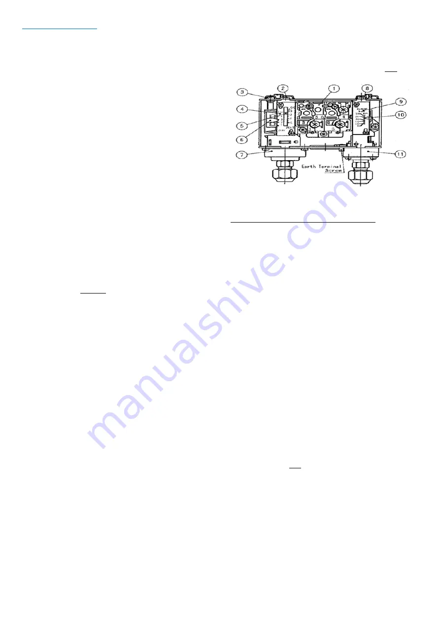
Dual Pressure Switch
The pressure switches fitted to condensing units with auto reset
for low pressure and manual reset for high pressure are
NOT
factory preset.
Setting Procedure for Dual Pressure Switch
High Pressure side
Turning the adjusting screw (8) clockwise will increase the cut-out
pressure setting. Turning the adjusting screw anti-clockwise will
decrease the cut-out pressure setting. The differential setting is
fixed so the cut-in will vary with the cut-out setting. Lock the
spindle with locking plate after setting.
Low pressure side
Range: Turning the range adjusting screw (2) clockwise will decrease
the cut-in pressure setting. Turning the range adjusting screw anti-
clockwise will increase the cut-in pressure setting.
Differential: Turning the differential adjusting screw (3) clockwise
will increase the differential pressure setting. Turning the
differential adjusting screw anti-clockwise will decrease the
differential pressure setting.
Lock the spindle with locking plate after setting.
Safety pressure switch settings
The Saginomiya dual pressure switch fitted to all JEH model
condensing units with auto reset for low pressure and manual reset
for high pressure is
NOT
factory preset.
BOTH THE LP AND HP
SWITCH SETTINGS MUST BE ADJUSTED TO SUIT THE APPLICATION
BEFORE STARTING THE UNIT.
Be sure that the high pressure setting
does not exceed the receiver’s maximum service pressure.
Содержание JEHR-0050-B1-M-1
Страница 13: ...Issue 01 05 2019 Page 13 Wiring Diagrams JEHR 0050 B1 M 1 JEHR 0067 B1 M 1 JEHR 0100 B1 M 1 JEHR 0113 B1 M 1 ...
Страница 14: ...Issue 01 05 2019 Page 14 Wiring Diagrams JEHR 0115 B1 L 1 JEHR 0135 B1 L 1 JEHR 0140 B2 M 1 ...
Страница 15: ...Issue 01 05 2019 Page 15 Wiring Diagrams JEHR 0140 B2 M 3 JEHR 0150 B2 M 1 JEHR 0175 B2 L 1 JEHR 0225 B2 L 1 ...
Страница 19: ...Issue 01 05 2019 Page 19 Wiring Diagrams JEHS 0750 B4 L 3 JEHS 0950 B4 L 3 EVI ...
Страница 20: ...Issue 01 05 2019 Page 20 Wiring Diagrams JEHS 1150 B4 L 3 EVI ...


