background image


Step 9 - 

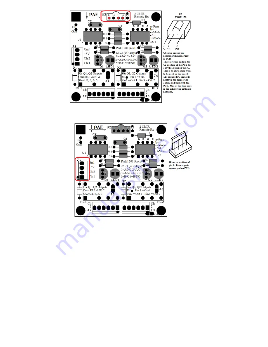
Insert J1.  Note the correct orientation.  Solder at 4 places. 


Assembly Options: 


Option 1.

  If only logic outputs are desired, the board is now complete.  Do not perform Option 2 or 3. 

 
O

ption 2.

  If relay outputs are desired, complete the following: 


Insert D1 and D2. The dark band shows orientation Solder at 4 places. 

Содержание 2171604

Страница 1: ...s see characteristics below Characteristics Operates with IR signals from 99 of existing IR remotes TV VCR cable DVD etc Learns remote code from the chosen remote transmitter no programming computer c...

Страница 2: ...tor 690582 1 Resistor 68 690726 2 Resistor 270 690961 2 Resistor 2 7 K 2081932 1 LED Orange Red diffused 696888 1 Switch 34657 1 LED Yellow diffused 2157167 3 Resistor 10 K 1 PCB 1 Instructions Step 1...

Страница 3: ...Step 3 Insert R5 R6 R7 and R8 Solder at 8 places Step 4 Insert C1 and C2 Solder at 4 places...

Страница 4: ...Step 5 Insert Q1 and Q2 Note the correct orientation flat side Solder at 6 places Step 6 Insert S1 Note the correct orientation Solder at 8 places...

Страница 5: ...TSOP1138 Note the correct orientation Also notice that there are extra solder pads in this location to allow other IR receiver ICs to be used The photo shows the correct position for the IC provided...

Страница 6: ...t 4 places Assembly Options Option 1 If only logic outputs are desired the board is now complete Do not perform Option 2 or 3 Option 2 If relay outputs are desired complete the following Insert D1 and...

Страница 7: ...Insert J2 See the instruction for J1 above for the correct orientation Solder at 6 places Insert RL1 and RL2 Note that the relays can only be inserted in one orientation Solder at 16 places...

Страница 8: ...ttons for that device Many devices do not use all the buttons on the remote so there would be no conflict if unused buttons were selected Some buttons may have no assigned code if so the LED will not...

Страница 9: ...on the tip of the iron to create a solder bridge D1 D2 RL1 and RL2 are not installed Outputs are taken from J3 as shown in the table above With no pull up resistors on the board the transistor outputs...

Страница 10: ...ransmitted It remains activated when that transmission ceases and additional transmissions of that Ch 1 code will not change the output state The channel 1 output is deactivated when the second Ch 2 c...

Отзывы: