5
C
A
B
D
E
G
H
F
I
6
1
2
3
4
5
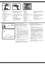
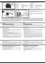
Vista laterale destra
1. Scatola di programmazione
2. Volante
3. Leva del gas
4. Vano Batterie
5. Presa di carica
6. Collegamentoper cavo Simulatore
Se si carica attraverso una presa, si prega di
aprire il coperchio della batteria. Viene usato
per il raffreddamento
Settore di programmzione
A. Direzione Reverse
B. Power LED
C. Direzione -Trim
D. Interruttore on /off
E. Gas Reverse
F. Power Check
G. Pulsante collegamen to Binde
H. Dual-Rate
I. Gas Trim
Trim
Se le ruote non puntano dritti in avanti, anche
se il volante della trasmettente è in posizione
neutrale, è possibile ottenere aiuto con il trim
della trasmittente nella posizione corretta.
Trim L/R = Sterzo
Se le ruote girano in avanti o indietro, anche se
nessun comando è stato dato attraverso il tras-
mettitore, poi anche l‘acceleratore deve essere
tagliato sul trasmettitore.
Trim V/R = Avanti / Indietro
Inserimento delle batterie
• Togliere il coperchio del scomparto batterie.
• Inserire 4 x AA batterie nella giusta
posizione, facendo attenzione ai poli.
• Rimettere il coperchio del scomparto
batterie.
Controls
1. Programming Box
2. Steering Wheel
3. Throttle Lever
4. Battery Hatch
5. Charge Socket
6. Simulator Cable Socket
If charging the batteries via the charging socket,
the battery hatch cover should be removed to
ensure sufficient cooling.
Programming Panel
A. Steering Reverse (changed)
B. Power LED
C. Steering Trim
D. ON/OFF Switch
E. Throttle Reverse (changed)
F. Power Check
G. Binding Button
H. Dual-Rate (maximum steering deflection)
I. Throttle Trim
Trim
If the wheels do not point straight forward even
though the steering wheel on the transmitter is
in neutral, you can adjust it with the trim button
on the transmitter.
Trim L/R = steering
Should the wheels rotate forward or backward,
even though no command was given through
the transmitter, then also the throttle needs to
be trimmed on the transmitter.
Trim V/R = forward/backward
Insert the batteries
• Remove the battery compartment cover.
• Fit the 4 x AA batteries, observe the correct
polarity.
• Replace the battery hatch
Trasmittente
Transmitter
Allacciare la trasmittente alla ricevente
In un moderno sistema di 2,4 GHz, è indispensabile che la
trasmittente e la ricevente vengano connesse insieme a bordo del
modello. La ricevente accetta quindi solo i segnali della
trasmittente. Se per qualsiasi motivo si dovesse effettuare un
nuovo allacciamento“connessione”, eseguire le seguenti
operazioni:
1. Sostituire nella trasmettente le batterie scariche con altre ca-
riche o nuove.
Lasciare spenta la trasmettente.
2. Inserire la spina di accoppiamento in dotazione nell’uscita del
canale 3.
3. Collegando la batteria con la ricevente, si accende il sistema
ricevente. l Led sulla ricevente inizia lampeggiare e cosiseg-
nala che la ricevente si trova in modalità di binding.
4. Tenere premuto il pulsante di connessione sulla trasmittente,
mentre si accende la stessa. E. Il trasmittente inizia a lam-
peggiare e cosi segnala che si trova in modalità di binding.
5. Rilasciare il pulsante di connessione della trasmettente e ri-
muovere la spina di connessione nella ricevente. Spegnere
laricevente e la trasmittente.
6. Adesso spegnete la trasmittente. Il sistema memorizza il col-
legamento.
7. Installare correttamente tutti gli accessori e controllare con
molta attenzione.
8. Se la funzione non avesse successo, ripetere la procedura
di connessione.
Vi incoraggiamo ora ad attivare l‘unità Failsafe incorporata del
vostro ricevitore.
Alla consegna è spento.
Montare l‘antenna 2.4 GHz verticalmente come mostrato nel
diagramma. Non permettete a nessun oggetto metallico di
entrare in contatto con l‘antenna o di schermarla perché questo
ridurrà la portata.
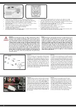
Binding the receiver to the transmitter
The receiver must be bound to the transmitter to ensure that the
receiver will only react to signals from that transmitter.
If you wish to re-bind the receiver with the transmitter please pro-
ceed as follows:
1. Put the battery into the model.
Now connect the battery to the speed control in the model.
2. Plug the binding plug (included) into the channel 3 socket on
the receiver.
3. Switch the receiver system on.
Depending on your soft-
ware version of your receiver indicates the different bin
-
ding mode (instead of flashing lights for example LED or
remains out completely).
The binding process as such is in
all versions. The receiver LED will begin to flash indicating
that the receiver is in bonding mode.
4. Press and hold down the binding button on the transmitter
whilst switching it on.
5.
The transmitter will begin to flash indicating that the receiver
is in bonding mode.
5. Release the binding button on the transmitter and turn off the
controller. Release the binding plug from the receiver.
7. Switch of the transmitter. And remove the binding wire. The
system be bound at the next start .
8. If the receiver fails to bond or does not function after bond-
ing repeat the above procedure until a successful bonding is
achieved.
We encourage you now to activate your receiver‘s built-in Failsafe
unit.
On delivery it is turned off.
Mount the 2.4 GHz antenna vertically as shown in the diagram. Do
not allow any metal object to come into contact with the antenna or
to shield it as this will reduce the range.
2,4 GHz
Antenna
Antenna
Ricevente/Receiver
Fail Safe
Setup LED
Connettore di
collegamento
Binding Plug
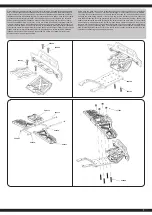
Содержание Monstertruck Crossmo EP
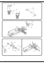
Страница 8: ...506135 506156 506185 505023 506155 506157 8...
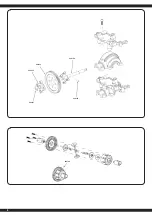
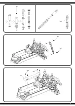
Страница 9: ...9 506112 059081 506145 059082 059081 506145 506147...
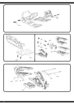
Страница 10: ...506134 059084 505090 505082 079996 505061 079989 505063 505084 506124 506134 505054 506147 10 505057 506128...
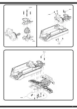
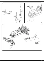
Страница 11: ...11 505064 505057 505053 059081 506149 506120...
Страница 13: ...13 506121 506121 506150 506145 506125 506125 079996 506133 505076 059078 059078...
Страница 14: ...505057 059081 059081 059082 506147 505054 506145 14...
Страница 15: ...15 505060 506141 505053 506131 059079 059081 506147 506118 059082 505058...
Страница 16: ...505060 506120 506120 505060 059109 503581 505187 503581 505187 503581 505187 505187 505058 16...
Страница 17: ...17 506143 506151...
Страница 18: ...18...


