File Version: 3.2
51
/
62
JAKA C Series Hardware User Manual
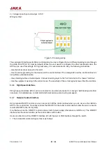
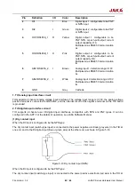
load is connected to the external input circuit, and the power positive electrode (red wire) is connected to the
external power supply.
Figure 5-24 PNP-type output wiring
4. RS485 signal circuit
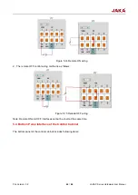
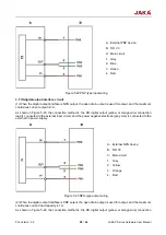
In the use of the RS485 function, the wiring method is: RS485+ is connected to RS485+ (yellow or brown wire),
RS48 is connected to RS48 (orange or white wire), the positive electrode is connected to the power positive
electrode (red wire), and the negative electrode is connected to the power negative electrode (gray wire), as
shown in Figure 5-25.
Figure 5-25 RS485 wiring
A
:
External PNP device
B
:
TIO V3
C
:
Main circuit
1.
Grey
2.
Yellow
3.
Orange
4.
Red
A
:
External device
B
:
TIO V3
C
:
Main circuit
1.
Grey
2.
Yellow
3.
Brown
4.
Orange
5.
White
6.
Red

