


GO-5100MC-PGE-1 | GO-5101MC-PGE-1 | User Manual (Ver. 1.0)
Main Functions
- 62 -
ROI (Region of Interest) Settings
Related Setting Items:
The ROI (region of interest) function allows you to output images by specifying the areas to scan.
ROI Settings
Specify the area to scan by specifying width, height, and horizontal/vertical offset values under [Image
Format Control]. For details on how to configure the settings, see “
”.
You can increase the frame rate by specifying a lower height, as the number of lines scanned
decreases. The minimum area is as follows.
Camera Model
Width
Height
GO-5100M-PGE-1
Binning Off: 16
Binning On: 8
4
GO-5101M-PGE-1
GO-5100C-PGE-1
16
4
GO-5101C-PGE-1
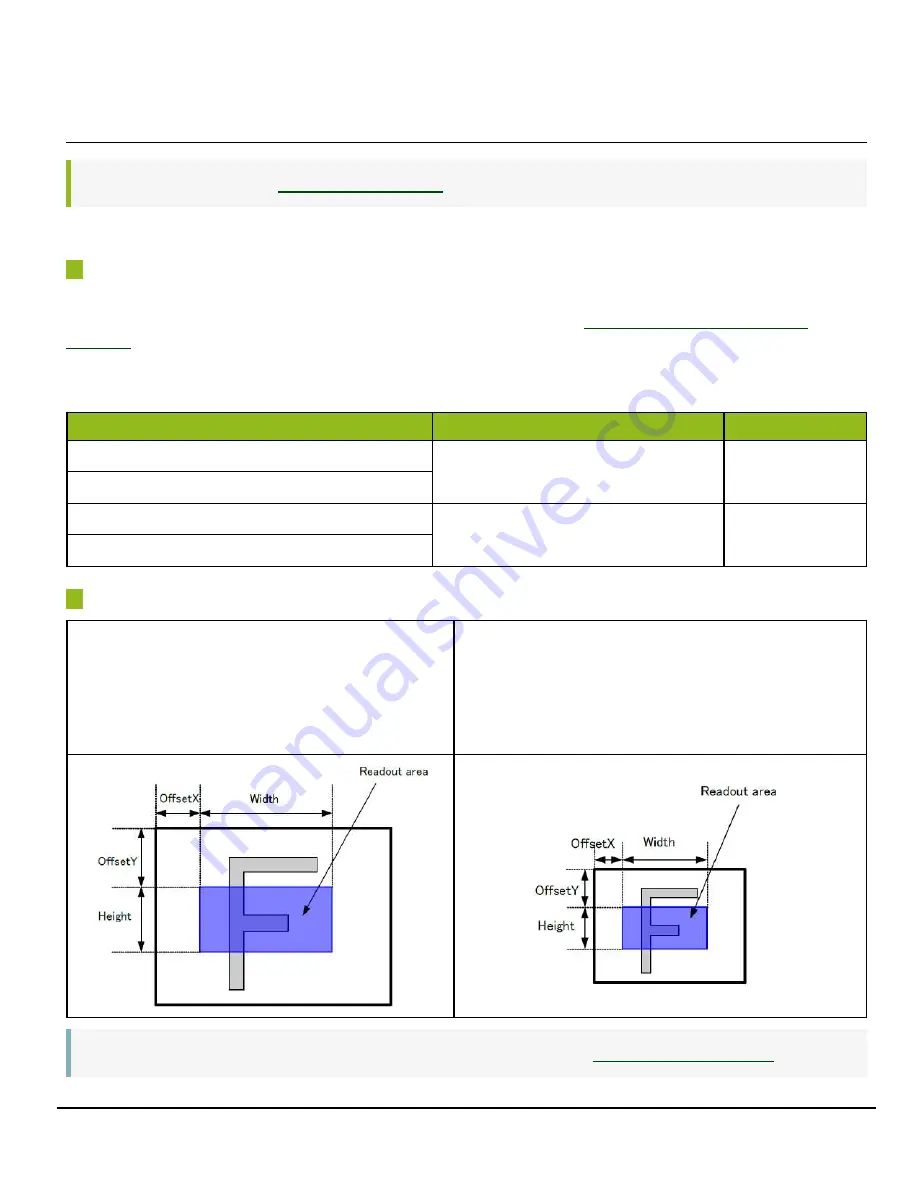
Examples
Setting Example: 1
Binning Horizontal = 1
Binning Vertical = 1
Width Max: 2464, Height Max: 2056
Setting Example: 2 (Monochrome models only)
Binning Horizontal = 2
Binning Vertical = 2
Width Max: 1232, Height Max: 1028
Note:
For details on the frame rates for common ROI sizes, see “
”.


