Pro II: Analog Input Modules
Pro II-AIn-32/18-D Rev. E
ADwin
26
ADwin-Pro
Hardware, manual version 2.9, June 2006
5.3.2 Pro II-AIn-32/18-D Rev. E
with an 18 bit ADC, 32 differ-
ential inputs and a programmable amplifier (PGA). The module can be com-
bined with amplifiers, Pro-TC and Pro-PT modules.
The module has 32 single-ended or 16 differential inputs (software selectable).
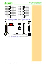
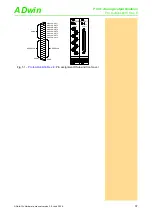
The inputs are equipped with with a 37-pin DSub socket; for pin assignment
see
and
After power-up the module is set to 16 differential inputs.
The module
has an input voltage range of ±10V and
a software selectable gain of 1, 2, 4 or 8. The adjustment of gain and offset is
done by software (see
chapter 6.3.1 "Calibration per Software"
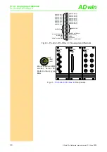
Ex works the inputs are connected to the ground of the Pro device. Alterna-
tively a GND level signal–common for all inputs–can be connected to one of
the AGND pins. The ground connection to the Pro device should be split up,
by switching the DIL switch (see
) to position
GND
LIFT
.
Do not run the module without ground connection.
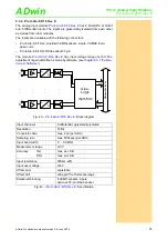
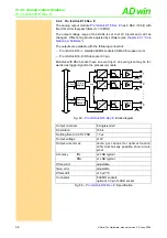
The module includes a sequential control, which can read measurement val-
ues from several or all input channels sequentially.
: Block diagram
.Input channels:
32 single ended or 16 differential;
via multiplexer
Resolution:
18 bit
Conversion time:
max. 2µs
Sampling rate:
max. 500ksps
Multiplexer settling time:
2.5µs
Measurement range:
±10V
Gain:
1, 2, 4, 8 software selectable
Accuracy
INL
±3 LSB typical
DNL
max. ±1 LSB
Input resistance:
330k
Ω
, ±2%
Input over-voltage:
±35V
Offset error:
adjustable
Offset drift:
±30ppm/ºC
Connector:
37-pin DSub socket
Fig. 34 –
: Specification
AD
w
in
-P
ro
I
I
bu
s
A
D
1
330k
330k
2
330k
330k
32
330k
330k
. .
.
.
. .
. .
.
Addr.
Data
Data
Registers
Data
PGA
V u= 1, 2, 4, 8
3
4
31
. . .
.
. .
. . .
MUX
Address
Decoder
Sequence
Control
Control


