Pro I: Signal Conditioning and Interface Modules
Pro-Fieldbus Modules
ADwin
176
ADwin-Pro
Hardware, manual version 2.9, June 2006
5.9.7 Pro-Fieldbus Modules
The fieldbus modules Pro-PROFI-DP-SL Rev. A and Pro-Inter-SL Rev. A pro-
vide a fieldbus interface with the functionality of a "slave". The modules have
a DP-RAM (Dual Port - Random Access Memory) with a size of 2kB. For the
user the communication is defined as access to this DP-RAM, the bus-specific
data exchange is realized with hardware. Therefore the communication is
more or less independent of the fieldbus type.
A fieldbus module occupies 32 addresses in the module goup EXT: The base
address set with the DIP switch block and the next 31 addresses. Details about
setting the DIP switch block and address numbers see
. By software,
the module is addressed via the base address only.
In the following text the characteristics of the fieldbus modules is described.
Later the special features of the fieldbusses are explained. The description is
divided into the following paragraphs:
–
Functions description of the fieldbus modules
–
–
–
–
–
Functions description of the fieldbus modules
Initialization
After switching on the Pro system the fieldbus interface must be initialized. The
module must not be accessed before the initialization. The initialization deter-
mines the size of the input and output areas and the behavior of the module.
A second initialization is not possible. If the interface is not correctly parame-
terized the Pro system must be switched on and off.
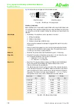
DP-RAM
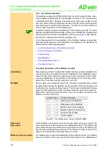
Each module has a DP-RAM (Dual Port - Random Access Memory), which
transfers data between the fieldbus and the program. Both, the program and
the fieldbus have access to this memory. The memory is divided into 6 large
areas and has a total size of 2kB. The table shows the areas of the memory.
Please take into account that the terms "input" and "output" are used as the
fieldbus controller sees them.
Fig. 307 – Pro-Fieldbus-SL: Areas of the DP-RAM
Data input /
Data output
In this address area data for cyclic and acyclic data exchange is saved. The
size of both areas is determined in the initialization phase. The data for the
cyclic data exchange is located at the beginning of each area, the data for the
acyclic data exchange follows directly. If the maximum memory size of 512
bytes is not obtained, the remaining area is not used.
Mailbox input and output
The mailbox area is used for initialization of the fieldbus module. The mailbox
area is the interface to the bus-specific part of the module. The initialization of
Address Area
Content / Function
000h - 1FFh
Data input (of the fieldbus)
200h - 3FFh
Data output (of the fieldbus)
400h - 51Fh
Mailbox input (of the fieldbus)
520h - 63Fh
Mailbox output (of the fieldbus)
640h - 7BFh
Fieldbus-specific data
7C0h - 7FFh
Control register

