ADwin-Pro-BM
ADwin
8
ADwin-Pro
Hardware, manual version 2.9, June 2006
4.3
ADwin-Pro-BM
Pro "backmounted" with
15 slots
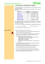
In the version "backmounted" of the standard enclosure, the modules are
plugged-in at the rear of the enclosure.
The revisions are similar to those of the
enclosure.
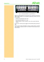
Fig. 6 – Enclosure of
ADwin-Pro I-BM
(rear panel)
Fig. 7 – Enclosure of
ADwin-Pro II-BM
(rear panel)
The system fuse is located in a slot in the power supply unit above the socket
for the power supply cable (rear of the enclosure).
At the rear of the enclosure, above the power supply connector you will find a
label with the revision number:
Number of Slots
16
Main dimensions (l x w x h)
Slot area (w x h)
336mm × 447.5mm × 146mm
84 HP × 3 U
Power supply unit
min. 70 W, 100 V…240 VAC at 50/60 Hz
switching power supply
Fuse
5A, delayed-action fuse
Fig. 8 – Enclosure of the
ADwin-Pro
-BM: Specification
Revision
Release
Previous versions
A
1997
First version with linear power supply.
B1
Sep. 1999
Prototype
(internal use only, not delivered to customers)
B2
Jun. 2003 Internal structure modified, function unchanged.
B3
Nov. 2003
New power supply (switching power supply) with
automatical voltage adaptation.
E1
Jun. 2005
ADwin-Pro II
: New enclosure design and new back
plane with Pro I and Pro II bus.
6
3
4
5
1
2
7
14
11 12 13
8
9
10
15
POWER
ON
230V
115 / 230 VAC
GND
6
3
4
5
1
2
POWER
ON
230V
115 / 230 VAC
GND
CPU-T11
ADwin-Pro
DIG I/O 0
EVENT IN
ST
BU
AC
LI
ET
HE
RN
ET
DIG I/O 1
7
14
11 12 13
8
9
10
4
1
2
3
5
7
5
6
8
9
10 11 12


