background image

Jacuzzi™ Addendum, Control Panel Electrical Requirements 

Page 2 of 2 

Publication GR86000A • 08-08

Heater

H

 2"

 L

 4"

 W

Blower Motor

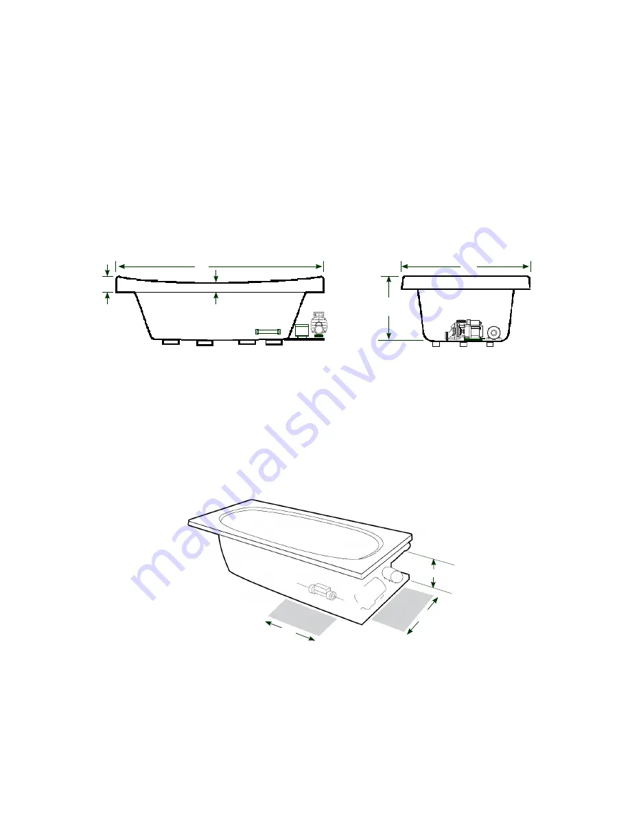
SIDE VIEW

END VIEW

Allusion

Pump Motor, Blower Service Access (Required)

FRONT

Heater

Blower

Motor

HEATER SERVICE AREA

MOTOR 

SERVICE

AREA

12"

  18"

18"

CAUTION

: Install all electrical services on the right side of the bath. The blower has been moved from the left 

side to the right side, next to the pump motor. 

The following details will replace information found in the Combination Air Bath and Whirlpool Installation and Operation 

Instructions, BR28000B (4/05) manual. 

NOTE

: The following art replaces the similar art found on 

Page 1 of the Combination Air Bath and Whirlpool manual. 

NOTE

: The following art replaces both pieces of similar art at the bottom of Page 3 of the manual. The art 

"Blower Service Access" shows the blower on the left end of the bath, but it has been moved to the right end, 

alongside the pump motor. 

Содержание Luxury/Designer Bath Series K339000X

Страница 1: ...uct registration card provided with your unit Write and save the model and serial number of your unit below Date Purchased ____________________________________________________________ Purchased From _...

Страница 2: ...N ELECTRIC SHOCK DO NOT USE THIS HYDROMASSAGE BATHTUB DISCONNECT THE HYDROMASSAGE BATHTUB AND HAVE THE PROBLEM CORRECTED BY A QUALIFIED SERVICE REPRESENTATIVE BEFORE USING WARNING FOR PERMANENTLY CONN...

Страница 3: ...BY THE MANUFACTURERS WARNING TOAVOIDINJURY EXERCISECAUTIONWHENENTERINGOREXITINGTHEHYDROMASSAGEBATHTUB WARNING KEEP BODY AND HAIR A MINIMUM OF 6 15 2 cm AWAY FROM SUCTION FITTING AT ALL TIMES WHEN THE...

Страница 4: ...______ 19 Clean Up After Installation _______________________________________________________________ 19 Operating Instructions __________________________________________________________________ 20 22...

Страница 5: ...he carrier For definitions of warranty coverage and limitations refer to the published warranty information packed with the product All bath units are factory tested for proper operation and watertigh...

Страница 6: ...ed P N P187000 16 1 4 413 mm A 13 1 2 343 mm B Factory Installed Intake S749000 Heater Factory Installed Intake S749000 Heater Factory Installed Intake S749000 Heater Factory Installed Intake S749000...

Страница 7: ...otected separate circuit SPECIFICATIONS DUETTA 7242 RH 72 1829 mm L 42 1067 mm W 26 660 mm H Template Provided P N DA06000 Not Available Factory Installed Intake S749000 Heater Min 98 U S gal 371 lite...

Страница 8: ...are nominal with a tolerance of 0 and 1 4 6 4 mm W H BELLAVISTA CORNER Right Hand SIDE VIEW END VIEW 2 51 mm Heater MAX 1 2 FOR ALL UNITS Electrical Service Requirements All require a dedicated GFCI p...

Страница 9: ...Access Opt Service Access BELLAVISTA 5 5 Right Hand 4 x 4 42 72 10 1 2 35 13 16 11 3 4 6 30 1 8 Heater Motor 12 H x 18 L Service Access Opt Service Access BELLAVISTA 6 Right Hand CIPREA Right Hand 4...

Страница 10: ...4 mm 10 Jacuzzi Whirlpool Bath K339000X 3 06 ROUGHING IN REFERENCE ELARA 6042 Right Hand 60 42 21 4 2 10 6 12 x 4 2 Heater Motor Opt Service Access 12 H x 18 L Service Access ELARA 6636 Right Hand 66...

Страница 11: ...REFERENCE RECTANGULAR Some tubs are supplied with cutout and or undermount template Refer to CUTOUT on pages 6 8 for template part numbers Add 1 4 to this dimension when roughing in for 3 wall niche N...

Страница 12: ...1 4 6 4 mm ROUGHING IN REFERENCE VENICIA Right Hand 10 1 2 36 3 42 72 12 1 8 5 1 4 29 7 8 18 x 4 Motor 12 H x 18 L Service Access Heater Opt Service Access 12 H x 18 L Service Access Opt Service Acce...

Страница 13: ...ments are in inches To convert to millimeters multiply inches by 25 4 3 Service access dimensions given are minimum size 4 The overall dimensions are nominal with a tolerance of 0 and 1 4 6 4 mm 60 60...

Страница 14: ...anchoring material is NOT used use construction adhesive under the foam feet and fasten the metal anchor straps to the floor to prevent the unit from shifting while trim deck finishes or finish caulk...

Страница 15: ...THOUT SKIRT 12 12 FRONT HEATER Service Access Corner Tubs For partially or fully sunken installations allow for ac cess to service connections It is the installer s respon sibility to provide sufficie...

Страница 16: ...e enough space to maneuver and insert tub The Designer Luxury line whirlpool tubs have electrical plumbing and lighting systems installed Do not lift the bath by the plumbing or wiring at any time han...

Страница 17: ...in the bottom illustration Do not use plumbing fixtures or plumbing lines to lower unit The clearance under the substrate is required for air flow circulation requirements Place a piece of scrap lumbe...

Страница 18: ...nfirm you have 120 VAC 20 AMP and 15 AMP service requirements The GFCI circuits must match these requirements Care must be taken to connect the 20 AMP pump motor or control box power cord ONLY to the...

Страница 19: ...ontrol the direction of the spray NOTE Proper installation of a shower is the responsibil ity of the installer Jacuzzi Whirlpool Bath is not respon sible for damage to the unit or for water damage whi...

Страница 20: ...ly Baths equipped with 2 speed motors and electronic controls can also influence water force and force of air Direction To change the direction of the water flow swivel the jet nozzle to the desired a...

Страница 21: ...om no air to maximum air Left Air Valve Status LED The Left Air Valve Status LED will show four LED lights at maximum air and only one LED light when the air is turned OFF Each additional LED indicate...

Страница 22: ...through the whirlpool system High Limit Switch The heater includes an exclusive High Limit switch This safety circuit will not false trip from hot tap water It will only turn off the heater if the th...

Страница 23: ...er and run for 2 to 3 minutes Drain completely and rinse off any residue Remember to reset the air valves to your bathing comfort level DANGER Harmful if swallowed Eye irritant Protect your eyes skin...

Страница 24: ...st always be in place on the suction fitting to minimize the potential hazard of hair and or body en trapment NOTCH GASKET COVER STRAINER SCREW SUCTION FITTING SUCTION COVER STRAINER ASSEMBLY Lighting...

Страница 25: ...junction box With motor turned off remove safety cover and remove any debris Clean thoroughly before replacing Replace suction cover before operating Use electronic controls to open air valves Reset...

Страница 26: ...2008 by Jacuzzi Whirlpool Bath Products Page of 2 Publication GR86000A 08 08 8 Button Control Panel SPECIFICATIONS FOR ALL UNITS Electrical Service Requirements Requires a separate dedicated GFCI prot...

Страница 27: ...rom the left side to the right side next to the pump motor The following details will replace information found in the Combination Air Bath and Whirlpool Installation and Operation Instructions BR2800...

Страница 28: ...n the wall of the bath near the pump motor Non jetted baths The label is located next to the overflow MODEL XXXXXXX NAME XXXXX COLOR XXXXX MFG XXXXX SER XXXXXX MADE IN USA THIS PRODUCT MEETS OR EXCEED...

Страница 29: ...as lightning floods earthquakes etc In addition THE COMPANY WILL NOT BE RESPONSIBLE FOR INCIDENTAL OR CONSEQUENTIAL DAMAGES or losses arising from any cause e g water damage to carpet ceiling loss of...

Страница 30: ...rum Dr Suite 400 Dallas TX 75254 Call 800 288 4002 To obtain warranty replacement for factory installed components for Company supplied options and accessories manufactured and supplied by the Company...

Отзывы: