J-100
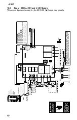
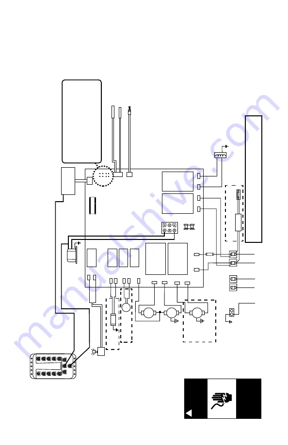
16.3 Export 50 Hz J-135 and J-145 Models
This wiring diagram is used for the 230V 50 Hz Export spa models.
DANGER
Turn power off before servicing. This task should only be performed by a quali
-
fied technician.
!
RISK OF SHOCK OR ELECTROCUTION!
Light DCU
1
2
3
4
5
6
7
8
9
10
POWER
EXP BAR
EXP BAR
BRN
BLU
C
Circ. Pump
Stereo
Power Supply
CLEAR
R
AY
GRN
TB1
BLU
BLU
J6
BRN J5
BRN
BLU
BLK
BLU
BRN
BLU
BRN
BLU
BLU
BRN
BRN
BRN
2
1
Flow Sensor
Hi - limit / freeze sensor
Temperature sensor
J1
J2
J3
F1 20A, 250V SC-20
Pump 1
Pump 2
Transformer
230 V
AC
J4
F1
JP1
4 2
3 1
6
5
8
7
HI
HI
LO
Control Panel
J20
K1
K2
K3
K4
K5
K6
K7
K8
J21
J11
J12
J13
J14
J15
J16
J17
J18
J19
J7
J8
J9
J10
Heater 2.7 kW @ 230 V
AC
WHT
BLK
LED Lighting System DCU
Logic Jumper Settings
JP1 1-2 ON =
20A
Logic
JP1 1-2 OFF =
30A
Logic
JP1 3-4 ON =
2 Pump Operation
JP1 3-4 OFF =
1 Pump Operation
JP1 5-6 ON =
40A
Logic (Remove JP1 1-2 Jumper)
JP1 5-6 OFF =
Leave Of
f for 20A
or 30A
Logic
JP1 7-8 ON =
Celsius
Temperature Display
JP1 7-8 OFF =
Fahrenheit
Temperature Display
Mini-Din Cable provides constant 12 V
AC from
yellow transformer wires
Mini-Din Control Panel Cable
Ports 1-10 power spa lights, waterfall lights and step lights on applicable models
OR
(not of
fered on
all models)
(not of
fered on all models)
(not o
ffered on all models)
TB2
BRN
BLU
230 V
AC 3-W
ire Connection
(50 Hz, 1-Phase Service), 1 Pump=15A/21A, 2 Pump=15A/29A,
USE COPPER CONDUCT
ORS ONL
Y.
WIRE SIZE MUST
MEET
NEC RECOMMENDA
TONS
AND/OR LOCAL
CODES
AND IS DETERMINED BY
MAXIMUM CURRENT
DRA
W
AND
LENGTH OF RUN.
(Not o
ffered on
all models)
40
Содержание J-145
Страница 1: ...J 100 COLLECTION OWNER S MANUAL 6530 592D Rev A J 145 J 135 J 125 J 115...
Страница 46: ...J 100 42...


