


en-3
JACOBSEN TR3
SAFETY, OPERATORS & MAINTENANCE MANUAL
1
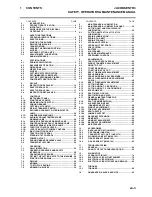
CONTENTS
CONTENTS
PAGE
CONTENTS
PAGE
2
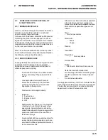
INTRODUCTION
2.2 PRODUCT
IDENTIFICATION ...................................... 4
2.1 IMPORTANT................................................................. 4
2.3
GUIDELINES FOR THE DISPOSAL
OF PRODUCTS ........................................................... 4
3
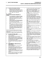
SAFETY INSTRUCTIONS
3.1
OPERATING INSTRUCTIONS..................................... 6
3.2
SAFETY SIGNS............................................................ 6
3.3
STARTING THE ENGINE............................................. 6
3.4
DRIVING THE MACHINE ............................................. 6
3.5
TRANSPORTING ......................................................... 6
3.6
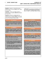
LEAVING THE DRIVING POSITION............................ 7
3.7
SLOPES ....................................................................... 7
3.8
BLOCKED CUTTING UNITS ....................................... 7
3.9 ADJUSTMENTS,
LUBRICATION
AND MAINTENANCE................................................... 7
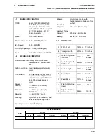
4
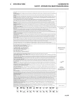
SPECIFICATIONS
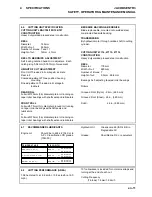
4.1
ENGINE SPECIFICATION ........................................... 9
4.2
MACHINE SPECIFICATION ........................................ 9
4.3
DIMENSIONS ............................................................... 9
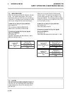
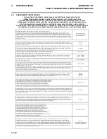
4.4
VIBRATION LEVEL.................................................... 10
4.5
SLOPES ..................................................................... 10
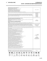
4.6
CUTTING UNIT SPECIFICATION.............................. 11
4.7
RECOMMENDED LUBRICANTS............................... 11
4.8
CUTTING PERFORMANCE (AREA) ......................... 11
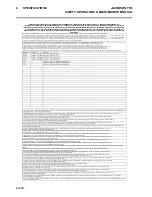
4.9
CONFORMITY CERTIFICATES................................. 12
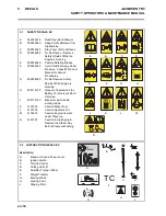
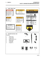
5
DECALS
5.2
INSTRUCTION DECALS EC...................................... 16
5.1
SAFETY DECALS EC ................................................ 16
5.3
SAFETY DECALS USA ............................................. 17
5.4
INSTRUCTION DECALS USA ................................... 17
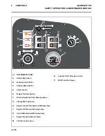
6
CONTROLS
6.1
INSTRUMENT PANEL ............................................... 18
6.1A
STARTER KEY SWITCH .......................................... 19
6.1B
WORKING LIGHT SWITCH ....................................... 19
6.1C
PARKING BRAKES ................................................... 19
6.1D
CUTTING UNIT SWITCH ........................................... 19
6.1E
WEIGHT TRANSFER SWITCH.................................. 20
6.1F
BLOCKED HYDRAULIC FILTER INDICATOR
LAMP.......................................................................... 20
6.1G
CHARGE WARNING LAMP....................................... 20
6.1H
ENGINE COOLANT TEMPERATURE
WARNING LAMP ....................................................... 20
6.1J
ENGINE OIL PRESSURE WARNING LAMP............. 20
6.1K
CONTROL MODULE FAULT WARNING LAMP ....... 21
6.1L
ENGINE PREHEAT INDICATOR LAMP.................... 21
6.1M
THROTTLE CONTROL LEVER ................................ 21
6.1N
JOYSTICK UNIT LIFT/LOWER CONTROL............... 21
6.1P
MULTI FUNCTION GAUGE ....................................... 22
6.2
TRACTION FOOT PEDAL ........................................ 23
6.3
STEERING TILT CONTROL ...................................... 23
6.4
POWER OUTLET ....................................................... 23
6.5
PARKING BRAKE RELEASE VALVE....................... 24
6.6
TRANSPORT LATCHES............................................ 24
7
OPERATION
7.1
DAILY INSPECTION .................................................. 25
7.2
OPERATOR PRESENCE AND SAFETY
INTERLOCK ............................................................... 26
7.3
OPERATING PROCEDURE....................................... 27
7.4
FITTING THE CUTTING UNITS TO THE MACHINE . 28
7.5
STARTING THE ENGINE .......................................... 29
7.6
DRIVING .................................................................... 29
7.7
MOWING .................................................................... 29
7.8
TO STOP THE ENGINE ............................................. 29
7.9
MOWING ON SLOPES .............................................. 30
8
MAINTENANCE & LUBRICATION
8.1
MAINTENANCE & LUBRICATION CHART .............. 34
8.2
CUTTING UNIT LMAC194/195/196/197
LUBRICATION ........................................................... 36
8.3
CUTTING UNITS 47114, 47115, 47116
LUBRICATION ........................................................... 37
8.4
ENGINE LUBRICATION ............................................ 38
8.5
ENGINE: FAN BELT .................................................. 38
8.6
ENGINE COOLANT ................................................... 39
8.7
HYDRAULIC SYSTEM............................................... 40
8.8
HYDRAULIC TEST PORTS ....................................... 41
8.9
FUEL SYSTEM........................................................... 42
8.11
BATTERY................................................................... 43
8.10
AIR CLEANER ........................................................... 43
8.12
MACHINE MAINTENANCE ....................................... 44
8.13
FREEWHEEL CONTROL .......................................... 44
9
ADJUSTMENTS
9.1
TRACTION CONTROL PEDAL ................................. 45
9.2
WEIGHT TRANSFER ADJUSTMENT ....................... 45
9.3
HEIGHT OF CUT........................................................ 46
9.4
TO SET REAR ROLL................................................. 46
9.5
TO SET HEIGHT OF CUT.......................................... 46
9.6
REEL TO BEDKNIFE ADJUSTMENT ....................... 47
9.7
REEL BEARINGS ...................................................... 47
9.8
FRONT AND REAR ROLL BEARINGS..................... 47
9.9
REEL-TO-BEDKNIFE (PRE-ADJUSTMENT
CHECK)...................................................................... 48
9.10
REEL-TO-BEDKNIFE ADJUSTMENT ...................... 49
9.11
CUTTING MODES...................................................... 50
9.12
CUTTING HEIGHT - FIXED MODE............................ 51
9.13
CUTTING HEIGHT - FLOATING MODE.................... 52
9.14
SPEED LIMITER ........................................................ 53
9.15
SEAT (MILSCO CE-200) ........................................... 53
9.16
SEAT (MICHIGAN V-5300) ....................................... 54
9.17
GENERAL INSTRUCTIONS FOR
GRAMMER SEATS.................................................... 55
9.18
SEAT (GRAMMER MSG85)....................................... 57
9.19
AIR SUSPENSION SEAT
(GRAMMER MSG75 -521) ......................................... 58
9.19.1
WEIGHT ADJUSTMENT............................................ 58
9.19.2
FORE/AFT ADJUSTMENT ........................................ 58
9.19.4
SEAT HEATER .......................................................... 59
9.19.5
LUMBAR SUPPORT.................................................. 59
9.19.3
BACKREST EXTENSION .......................................... 59
9.19.6
ARMRESTS................................................................ 60
9.19.7
ARMREST ADJUSTMENT ........................................ 60
9.19.8
BACKREST ADJUSTMENT ...................................... 60
9.19.9
MAINTENANCE ......................................................... 61
10
ACCESSORIES
10.1
BACKLAPPING KIT (LMAC161).............................. 62
10.2
OPS FRAME (LMAC164).......................................... 63
10.3
TRANSPORT LATCH KIT (LMAC174)..................... 63
10.4
WORKING LAMP KIT (LMAC163) ........................... 63
10.5
GRASS BOX KIT (LMAC182 ).................................. 63
10.6
GRASS BOX KIT (LMAC193 ).................................. 63
11
TROUBLESHOOTING
11.1
GENERAL .................................................................. 64
11.2
QUALITY OF CUT TROUBLESHOOTING ................ 65
12
SCHEMATICS
12.1
HYDRAULIC CIRCUIT ............................................... 74
12.2
ELECTRICAL CIRCUIT INSTRUMENT..................... 76
12.3
ELECTRICAL CIRCUIT MAIN ................................... 78
12.4
ELECTRICAL CIRCUIT FUSES AND RELAYS ........ 80
13
TORQUES
13.1
TORQUES .................................................................. 82
14
GUARANTEE / SALES & SERVICE.......................... 83
Содержание TR3 EJ Series
Страница 2: ...2010 Ransomes Jacobsen Limited All Rights Reserved...
Страница 33: ...en 33 JACOBSEN TR3 SAFETY OPERATORS MAINTENANCE MANUAL 7 OPERATION...
Страница 35: ...en 35 JACOBSEN TR3 SAFETY OPERATORS MAINTENANCE MANUAL 8 MAINTENANCE LUBRICATION...
Страница 73: ...en 73 JACOBSEN TR3 SAFETY OPERATORS MAINTENANCE MANUAL 11 TROUBLESHOOTING...
Страница 74: ...en 74 JACOBSEN TR3 SAFETY OPERATORS MAINTENANCE MANUAL 12 1 HYDRAULIC CIRCUIT 12 SCHEMATICS...
Страница 78: ...en 78 JACOBSEN TR3 SAFETY OPERATORS MAINTENANCE MANUAL 12 3 ELECTRICAL CIRCUIT MAIN 12 SCHEMATICS...
Страница 84: ......
Страница 85: ......


