6 OPERATION
12
6
OPERATION
6.1 DAILY INSPECTION________________________________________________________
1. Perform a visual inspection of the entire unit, look for
signs of wear, loose hardware, and missing or
damaged components. Check for fuel or oil leaks.
2. Check the fuel supply and crankcase oil level. All
fluids must be at the full level mark.
3. Make sure the mower is adjusted to the required
cutting height.
4. Make sure the machine is lubricated and the
transport tires are properly inflated.
5. Check the O.P.C. system (Section 6.2).
6.2
OPERATOR PRESENCE CONTROL __________________________________________
1. The O.P.C. system is intended to protect the
operator and others from injury by stopping the reel
and drive mechanism as soon as the operator
releases the O.P.C. bail. The unit is also equipped
with an engine stop (E-Stop) switch that will stop the
engine from the operator’s position.
2. To test the system:
a. Place mower on the kickstand.
b. Disengage the reel clutch lever
(E)
.
3. Start the engine.
a. Slide bail to the left and engage OPC Bail.
b. Engine speed will increase, the drive mechanism
will engage and the wheels will begin to turn.
c. Release the O.P.C. bail. The bail must
disengage, engine speed return to idle and drive
mechanism must stop.
d. Push E-Stop switch down. Engine must stop
immediately.
4. If the drive mechanism engages before the O.P.C.
bail is engaged or the drive mechanism continue to
turn after the O.P.C. bail is released; stop the
engine immediately and have the system repaired.
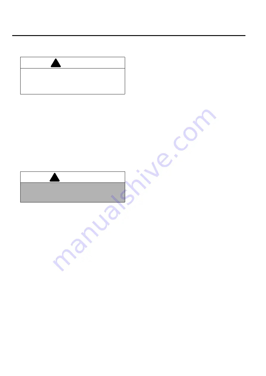
CAUTION
The daily inspection should be performed only
when the engine is off and all fluids are cold.
Disengage all drives, engage parking brake, stop
engine and disconnect spark plug wire.
!
WARNING
Never operate equipment with the O.P.C. system
disconnected or malfunctioning. Do not
disconnect or bypass any switch.
!
Содержание PGM 22
Страница 28: ...9 NOTES 28 9 NOTES ...
Страница 29: ...NOTES 9 29 ...
Страница 56: ...9 NOTER 28 9 NOTER ...
Страница 62: ...5 8 9 10 11 18 4 3 4 5 6 7 18 20 1 2 19 20 12 13 14 15 16 17 PGM 3 1 Left Chain Cover Serial No All ...
Страница 66: ...9 8 9 6 5 1 2 4 7 21 13 20 19 18 3 4 10 11 12 13 14 15 16 17 PGM 5 1 Right Side Frame Serial No All ...
Страница 74: ...17 17 14 15 12 13 10 20 21 11 5 5 3 18 19 23 16 2 3 1 4 6 7 8 9 22 22 PGM 9 1 Transport Wheels Serial No All ...
Страница 76: ......
Страница 77: ......


