


Tempstar LT/NB/S/SDS Technical Manual 7610-011-86-35
Issued: 12-07-2007 Revised: N/A
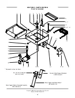
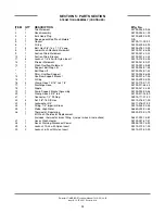
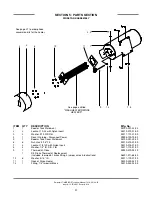
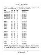
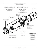
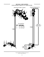
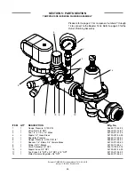
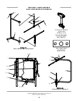
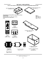
SECTION 5: PARTS SECTION
TEMPSTAR INCOMING PLUMBING/OUTLET PLUMBING ASSEMBLY/WPRK KIT OPTION
44
ITEM
QTY
DESCRIPTION
Mfg. No.
1
1
Water Pressure Regulator, 3/4" NPT
06685-011-58-22
2
1
Valve, Ball, 1/4" NPT
04810-011-72-67
3
1
Gauge, Pressure, 0-100 PSI
06685-111-88-34
4
2
Nipple, Close, 3/4" NPT
04730-207-34-00
5
1
Tee, Brass, 3/4" NPT x 3/4" NPT x 1/4" NPT
04730-211-04-00
6
1
Valve, Solenoid, 3/4" NPT
04810-100-03-18
7
1
Nipple, Brass, 3/4" NPT x 2" Long
04730-207-46-00
8
1
Elbow, 3/4" NPT, Brass, Street
04730-206-04-34
9
3
Union, 3/4" NPT, Brass
04730-212-05-00
O-ring
05330-003-
10
6
Adapter, 3/4" Male
04730-401-11-01
11
1
Tube, Copper
See Chart
12
2
Elbow, 3/4" CU x CU, 90
°
04730-406-16-01
13
2
Adapter, 3/4", 604-2
04730-401-10-01
14
1
Tube, Copper
See Chart
15
1
Vacuum Breaker, 3/4" NPT
04820-002-53-77
16
1
Tube, Copper
See Chart
17
1
Elbow, 3/4" NPT, 90
°
, Brass
04730-206-13-00
18
1
Tube, Copper
See Chart
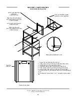
When servicing plumbing components, take care not to damage the threads of each individual item. Damaged threads can
cause leaks and loss of pressure, which could adversely effect the performance of the Tempstar dishmachine. It is strongly rec-
ommended that teflon thread tape, used in conservative amounts, be applied to threads when joining components together. It
is not advised to use thread sealing compounds, sometimes referred to as “pipe dope”. Compounds can be ejected from the
threads during the tightening process and become lodged in key components, thereby rendering them useless. Some of the
components include the solenoid valve and the pressure gauge isolation ball valve.
Water Arrestor, 1/2”
06685-100-05-00
Tee, 3/4” x 3/4” x 1/2”
04730-211-06-00
Nipple, 3/4” NPT, Close, Brass
04730-207-34-00
WPRK KIT OPTION
Содержание TEMPSTAR
Страница 2: ......
Страница 9: ...1 SECTION 1 SPECIFICATION INFORMATION ...
Страница 16: ...8 SECTION 2 INSTALLATION OPERATION INSTRUCTIONS ...
Страница 22: ...14 SECTION 3 PREVENTATIVE MAINTENANCE ...
Страница 24: ...16 SECTION 4 TROUBLESHOOTING SECTION ...
Страница 27: ...19 SECTION 5 PARTS SECTION ...
Страница 67: ...59 SECTION 6A ELECTRICAL SCHEMATICS FOR TOP MOUNT UNITS ...
Страница 83: ...75 SECTION 6B ELECTRICAL SCHEMATICS FOR SIDE MOUNT UNITS ...
Страница 93: ...85 SECTION 6C ELECTRICAL SCHEMATICS FOR OPTIONS ...
Страница 96: ...88 SECTION 7 JACKSON MAINTENANCE REPAIR CENTERS ...
Страница 103: ......