Jackson Hot Water Sanitizing Undercounter Dishmachines... Скачать руководство пользователя страница 13

PREPARATION:

Before proceeding with the start-up of the unit, verify the following:

1. The strainer is in place and is clean.
2. That the wash and rinse arms are screwed securely into place and that their endcaps are tight. The wash and rinse

arms should rotate freely.

POWER UP:

To energize the unit, turn on the power at the service breaker. The voltage should have been previously verified

as being correct. If not, the voltage will have to be verified.

FILLING THE WASH TUB:

For the initial fill, close the door and depress the ON/FILL-OFF/DRAIN rocker switch in the ON posi-

tion. The machine will run a partial cycle and fill to the factory preset level.  Open  the door and verify that the water level is
correct.  Hereafter, the water level is controlled by the timer that has been preset at the factory.  Verify that there are no other
leaks on the unit before proceeding any further. The wash tub must be completely filled before operating the wash pump to pre-
vent damage to the component. Once the wash tub is filled, the unit is ready for operation.

NOTE: This applies to units with integral booster heaters. Make sure the orange wires at the heater contactor are con-
nected properly. They have been purposely disconnected at the factory to avoid damage to the heater element when
there is no water in the booster heater.

The machine runs a complete cycle to drain and fill. If the machine is not allowed to drain, the water will build up inside the tub.
After the initial fill, the rinse water for the current cycle will become the wash water for the next cycle.

WARE PREPARATION:

Proper preparation of ware will help ensure good results and less re-washes. If not done properly, ware

may not come out clean and the efficiency of the dishmachine will be reduced. It is important to remember that a  dishmachine
is not a garbage disposal and that simply throwing unscraped dishes into the machine simply defeats the purpose altogether
of washing the ware. Scraps should be removed from ware prior to being loaded into a rack. Pre-rinsing and pre-soaking are
good ideas, especially for silverware and casserole dishes. Place cups and glasses upside down in racks so that they do not
hold water during the cycle. The dishmachine is meant not only to clean, but to sanitize as well, to destroy all of the bacteria
that could be harmful to human beings. In order to do this, ware must be properly prepared prior to being placed in the machine.

DAILY MACHINE PREPARATION:

Refer to the section entitled “PREPARATION” at the top of this page and follow the instruc-

tions there. Afterwards, check that all of the chemical levels are correct and/or that there is plenty of detergent available for the
expected workload.

WARM-UP CYCLES:

For a typical daily start-up, it is recommended to run the machine through 3 cycles to ensure that all of

the cold water is out of the system and to verify that the unit is operating correctly. To cycle the machine, ensure that the power
is on and that the tub has filled to the correct level. Open the door and the cycle light will illuminate. 

When the light goes out, close the door, the unit will start, run through the cycle, and shut off automatically. Repeat this two
more times. The unit should now be ready to proceed with the washing of ware.

WASHING A RACK OF WARE:

To wash a rack, open the door completely and slide the rack into the unit. Close the door and

the unit will start automatically. Once the cycle is completed, open the door and remove the rack of clean ware. Replace with
a rack of soiled ware and close the door. The process will then repeat itself.

OPERATIONAL INSPECTION:

Based upon usage, the pan strainer may become clogged with soil and debris as the workday

progresses. Operators should regularly inspect the pan strainer to ensure it has not become clogged. If the strainer does, it will
reduce the washing capability of the machine. Instruct operators to clean out the pan strainer at regular intervals or as required
by work load.

SHUTDOWN AND CLEANING:

At the end of the workday, close the door. Start a cycle, then place the ON/FILL - OFF/DRAIN

SWITCH  to the “ OFF/DRAIN” position. The unit will automatically drain and turn off. Once the wash tub is drained, remove he
pan strainer. Remove soil and debris from the strainer and set to the side. Unscrew the wash and rinse arms from their mani-
folds. Remove the endcaps and flush the arms with water. Use a brush to clean out the inside of the arms. If the nozzles appear
to be clogged, use a toothpick to remove the obstruction. Wipe the inside of the unit out, removing all soil and scraps.
Reassemble the wash and rinse arms and replace them in the unit. The arms only need to be hand tight, do not use tools to
tighten them down. Reinstall the strainer and close the door. 

JP-24 Technical Manual 7610-002-49-79 Rev. D

Issued: 03-06-2006  Revised: N/A

SECTION 2: INSTALLATION/OPERATION INSTRUCTIONS

OPERATION INSTRUCTIONS 

8

Содержание Hot Water Sanitizing Undercounter Dishmachines...

Страница 1: ...MESTIC UNITS FOR JACKSON MODELS JP 24 JP 24F JP 24B JP 24BF An Company HOT WATER SANITIZING UNDERCOUNTER DISHMACHINES March 6 2006 P N 7610 002 49 79 Revision D Jackson MSC Inc P O BOX 1060 HWY 25E BA...

Страница 2: ......

Страница 3: ...W 6836 Updated per ecns D 03 06 2006 MAW 7421 7231 6964 7095 Change thermostat from 05930 121 71 29 to 05930 510 03 79 Change thermostat from 05930 121 71 36 to 05930 011 49 43 Change Diverter Valve A...

Страница 4: ...ial No Installation Date Service Rep Name Phone No Jackson MSC Inc provides technical support for all of the dishmachines detailed in this manual We strongly recommend that you refer to this manual be...

Страница 5: ...lectrical Panel Assembly JP 24B BF 460 Volt 60Hz 32 Gauge Panel Assembly Used with the external mounted control panel assemblies 34 Electrical Panel Assembly External AMTRAK Option 34 Kick Plate Assem...

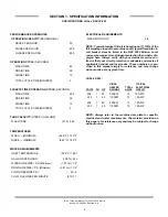
Страница 6: ...1 SECTION 1 SPECIFICATION INFORMATION...

Страница 7: ...FLOW GALLONS PER MINUTE 27L 7 1 ELECTRICAL REQUIREMENTS WASH MOTOR HP 3 4 NOTE Typical Electrical Circuit is based upon 1 125 of the full amperage load of the machine and 2 typical fixed trip cir cui...

Страница 8: ...CAL REQUIREMENTS WASH MOTOR HP 3 4 NOTE Typical Electrical Circuit is based upon 1 125 of the full amperage load of the machine and 2 typical fixed trip cir cuit breaker sizes as listed in the NEC 200...

Страница 9: ...nside Clearance Height 14 1 2 36 8 cm Height maximum 34 1 4 87 cm Inside Clearance Width 20 1 4 51 4 cm Width 24 60 9 cm Inside Clearance Depth 21 1 4 54 cm Depth 22 5 8 57 5 cm Door Open Depth 39 1 2...

Страница 10: ...SECTION 2 INSTALLATION OPERATION INSTRUCTIONS 5...

Страница 11: ...eign matter left in the water line and any expenses resulting from this fouling are not the responsibility of the manufacturer CONNECTING THE DRAIN LINE The JP 24 series machines are a pumped pressure...

Страница 12: ...ock Install the grounding wire into the lug provided It is recommended that DE OX or another similar anti oxidation agent be used on all power connections VOLTAGE CHECK Ensure that the power switch is...

Страница 13: ...er to do this ware must be properly prepared prior to being placed in the machine DAILY MACHINE PREPARATION Refer to the section entitled PREPARATION at the top of this page and follow the instruc tio...

Страница 14: ...for operators Using too much detergent has as detrimental effects as using too little The proper amount of detergent must be used for job It is important to remember that certain menu items may requi...

Страница 15: ...6 Assemble the counter with mounting plate to the control panel using the four screws and locknuts provided 7 One lead wire from the counter is connected together with the blue wires from the fill sol...

Страница 16: ...SECTION 3 PREVENTATIVE MAINTENANCE 11...

Страница 17: ...mind operators that trying to perform corrective maintenance on the dishmachine could lead to larg er problems or even cause harm to the operator If a problem is discovered secure the dishmachine usin...

Страница 18: ...SECTION 4 TROUBLESHOOTING 13...

Страница 19: ...through the rinse arms when the ON FILL switch is depressed 1 Water not turned on Turn water on 2 Defective solenoid valve Replace solenoid valve 3 Probes are dirty or coated Clean probes 4 Defective...

Страница 20: ...em Rinse water not at required temperature range 1 Thermometer is defective Replace 2 Thermostat is defective Adjust the thermostat Replace if necessary Problem Machine doesn t drain when OFF DRAIN sw...

Страница 21: ...16 SECTION 5 SERVICE PROCEDURES...

Страница 22: ...D It is estimated that it will take 1 person twenty min utes to perform this task not including all of the items indicat ed in the section entitled PREPARATION IMPORTANT NOTES 1 Read these instruction...

Страница 23: ...coil Take the new coil and attach the conduit reinstall tighten the conduit nut and pull the wires through so that you will be able to wire the valve back up 9 Reconnect the wires from the conduit to...

Страница 24: ...ad it is recommended that the entire valve should be replaced These instructions do not provide information on replacing the solenoid valve 16 Note Even though an O ring may not appear damaged it is a...

Страница 25: ...fective replacement parts with new parts from ordered kits Ensure that components are sufficiently tightened to prevent leakage AFTER MAINTENANCE ACTIONS Reconnect the incoming water if disconnected a...

Страница 26: ...n 1 Small flathead screwdriver 2 Needle nose pliers TIME REQUIRED It is estimated that it will take 1 person twenty min utes to perform this task not including all of the items indicat ed in the secti...

Страница 27: ...soft towel remove any grit grime or debris that may have gotten caught in the threads of both the cap retainer or the vacuum breaker body There is an O ring that should be present on the cap retainer...

Страница 28: ...above REPLACING THE BOOSTER TANK HEATER The following list of tools will be needed to complete this procedure phillips screwdriver and 1 2 socket and ratchet 1 Disconnect the electrical power to the...

Страница 29: ...into pan The dishmachine may be drained by opening the petcock on the pump housing or by removing the wash thermometer bulb from the lower wash tank 7 Use a 5 16 nutdriver to loosen the hose clamp an...

Страница 30: ...moved if applicable 4 Remove any and all access covers TOOLS REQUIRED The following tools may be needed to perform this maintenance evolution 1 3 8 Nutdriver 2 7 16 Combination Wrench 3 Needlenose Pli...

Страница 31: ...ounting nuts with the 3 8 nutdriver 5 Attach the jumper wires to the wires that you removed from the old thermostat Removing the imperial brass fitting Tempstar Location of the thermostat bracket JP 2...

Страница 32: ...ostat so that it does not hang over the heater 9 Note regardless of the unit this is being done to the con cept is to ensure that the thermostat cannot come into contact with the heater leads or inter...

Страница 33: ...is installed it will be nece sary to ensure that it operates at the required and appropriate ranges The new thermostat has an adjustment that can be turned using a small flathead screwdriver Several c...

Страница 34: ...SECTION 6 PARTS SECTION 29...

Страница 35: ...eter 96 Wash 06685 111 68 49 8 1 Thermometer 48 Rinse 06685 111 68 48 9 1 Switch ON FILL OFF DRAIN 05930 301 49 55 10 1 Light Red 05945 111 44 45 11 1 Switch Delime 05930 011 49 00 12 1 Light Amber 05...

Страница 36: ...ket Relay Mounting 05700 002 37 85 11 1 Relay 220 240 Volt 05945 111 89 75 12 4 Screw 6 32 x 3 8 Sems with External Tooth Lockwasher 05305 002 25 91 13 1 Decal Timer 09905 011 40 70 14 1 Timer 60 HZ 0...

Страница 37: ...9905 101 40 82 10 1 Contactor Heater 05945 002 74 20 11 1 Decal Timer 09905 011 40 70 12 1 Timer 60 HZ 05945 121 41 60 12 1 Timer 50 HZ 05945 002 13 34 12 1 Timer 5 Minute 05945 121 44 89 13 2 Screw 6...

Страница 38: ...940 200 76 00 12 1 Ground Decal 09905 011 41 82 13 1 Overload Contactor 05945 111 60 08 14 1 ACME Transformer 480 to 120 Volt 05950 011 50 70 15 1 Terminal Board 1 4 QC 05940 021 94 85 16 2 Screw 6 32...

Страница 39: ...9905 031 73 94 6 1 Fitting 1 4 BARB x 1 4 FNPT Swivel 04730 011 95 42 7 1 Hose 5 16 x 12 05700 011 86 45 8 1 Fitting 1 4 BARB x 1 4 MNPT Swivel 04730 011 95 41 JP 24 Technical Manual 7610 002 49 79 Re...

Страница 40: ...EXTERNAL OPTION AMTRAK OPTION 35 13 12 7 FRONT VIEW EXTERNAL OPTION INSIDE VIEW of AMTRAK EXTERNAL OPTIONS Electrical Component Mounting Bracket 05700 031 84 85 Control Box Mounting Panel Amtrack Opti...

Страница 41: ...Motor 05945 002 74 20 6 1 Panel Inner Control Box 05700 031 91 51 7 9 Screw 10 32 x 3 8 Phillips Truss Round Head 05305 173 12 00 8 1 Track Terminal 3 5 16 05700 000 43 60 9 2 Block Snap in Terminal 0...

Страница 42: ...ckplate Weldment 05700 041 86 40 Control Panel Assembly 05700 011 40 93 Control Panel Only 09330 041 41 94 460 Control Panel Assembly 05700 002 18 38 460 Control Panel Only 09330 041 85 00 Nut Nylon W...

Страница 43: ...2 x 19 1 2 05700 011 59 84 10 1 Copper Tube 1 2 x 4 1 2 05700 011 59 83 11 1 Copper Tube 1 2 x 25 1 2 05700 011 59 85 12 1 Adapter 1 2 Ftg x Male 04730 401 03 01 JP 24 Technical Manual 7610 002 49 79...

Страница 44: ...1 44 34 9 1 Elbow 1 2 90 C to MSPS 04730 406 32 01 JP 24 Technical Manual 7610 002 49 79 Rev D Issued 03 06 2006 Revised N A SECTION 6 PARTS SECTION INCOMING PLUMBING ASSEMBLIES JP 24B JP 24BF 39 1 7...

Страница 45: ...6 PARTS SECTION RINSE STIFFENER RINSE HUB WELDMENT 40 Rinse Hub Weldment 05700 021 38 31 Rinse Tube Stiffener 05700 011 44 32 Vellumoid Rinse Gasket 05330 111 42 81 Clamp Hose 04730 719 06 09 Hose 3...

Страница 46: ...only 1 2 06401 003 07 44 Screw Data Plate Coil Housing Valve Bonnet Spring Plunger Kit 06401 003 07 40 Spring position is moved for clarity Goes below the plunger O Ring Diaphragm 06401 003 07 41 Dia...

Страница 47: ...02 5 4 Tricnut 10 32 AK Fastener S S 05340 111 58 10 6 1 Lockwasher 10 External Tooth 05311 273 02 00 7 1 Grommet Heyco 05975 210 03 00 8 1 Cam Weldment 05700 011 65 78 9 1 Plate Dielectric 05700 011...

Страница 48: ...d Truss Head 05305 173 04 00 4 1 Diverter Valve Assembly 115 Volt 06401 012 23 21 4 1 Diverter Valve Assembly 220 Volt 06401 022 23 21 5 1 Clamp 11 16 to 1 1 4 04730 002 18 40 6 1 Hose 1 I D x 10 Feet...

Страница 49: ...Gasket 4 75 x 4 09 x 1 16 05330 111 59 90 Gasket 4 75 x 4 09 x 1 64 05330 002 42 86 JP 24 Technical Manual 7610 002 49 79 Rev D Issued 03 06 2006 Revised N A SECTION 6 PARTS SECTION WASH MOTOR TO WASH...

Страница 50: ...Imperial Brass 05310 924 02 05 Thermostat Rinse Tank 05930 510 03 79 Kit Rinse Thermostat Replacement Includes thermostat brass fitting 2 jumper wires instructions 06401 011 66 55 Nut 5 16 18 S S Hex...

Страница 51: ...01 44 75 11 1 Seal Channel Inner Door Right 05700 031 32 91 12 1 Latch Assembly 05700 011 44 41 13 1 Inner Door 05700 031 32 85 14 1 Seal Channel Inner Door Top 05700 031 32 90 15 12 Fastener Screw 10...

Страница 52: ...Casting 05700 011 44 40 Latch Roller 05700 011 44 38 Latch Spring 05700 011 44 39 Door Latch Assembly 05700 011 44 41 Stop Left Hinge 05700 021 37 67 Stop Right HInge 05700 021 37 68 Cover Right HInge...

Страница 53: ...own 05330 002 60 69 Rinse Arm 05700 031 38 30 Plug Rinse Arm 04730 609 04 00 Bushing Rinse Head 05700 021 33 84 Bearing 03120 002 72 24 Ring Retaining 05340 112 01 11 Wash Arm Weldment 05700 021 46 58...

Страница 54: ...ith Nut Nylon Wing 1 4 20 05310 994 01 00 Strainer Weldment 05700 031 35 81 Right Frame Weldment 05700 011 73 86 Left Frame Weldment 05700 011 73 85 Top Panel 05700 041 38 38 Left Dress Panel 05700 04...

Страница 55: ...mplate in order to cut away the cutout 5 Remove the template from the control panel 6 Assemble the counter with mounting plate to the control panel using the four screws and locknuts provided 7 One le...

Страница 56: ...51 SECTION 7 ELECTRICAL SCHEMATICS...

Страница 57: ...JP 24 Technical Manual 7610 002 49 79 Rev D Issued 03 06 2006 Revised N A SECTION 7 ELECTRICAL SCHEMATICS JP 24 JP 24F 208 230 VOLT 50 60 HERTZ SINGLE PHASE 52...

Страница 58: ...JP 24 Technical Manual 7610 002 49 79 Rev D Issued 03 06 2006 Revised N A SECTION 7 ELECTRICAL SCHEMATICS JP 24B JP 24BF 208 230 VOLT 50 60 HERTZ SINGLE PHASE 53...

Страница 59: ...JP 24 Technical Manual 7610 002 49 79 Rev D Issued 03 06 2006 Revised N A SECTION 7 ELECTRICAL SCHEMATICS JP 24B JP 24BF 460 VOLT 60 HERTZ THREE PHASE 54...

Отзывы: