


WARNING: Inspection, testing and repair of electrical equipment should only be performed by a qualified service techni-
cian. Many of the tests require that the unit have power to it and live electrical components be exposed.
USE EXTREME CAUTION WHEN TESTING THE MACHINE.
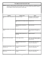
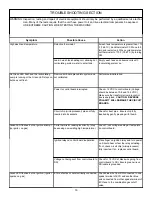
TROUBLESHOOTING SECTION
17
Possible Cause
Action
Gas flow interrupted.
Check manual gas valve is open.
Check regulated gas pressure. (4.0 -6.0
WCI) for town gas.
If gas line diameter is less than 1/2"
(1.27cm) or gas line greater than 16 feet
(4.88m), reduce pressure may result.
Combination gas cutoff valve is closed.
Ensure 12 VDC to both sides of valve. If
not, check ECO and DSI. If yes, valve may
have failed shut. Replace valve.
Modulating valve forced out of normal range
and may be stuck (common occurrence
during shipment).
Tap on gas supply line between the
combination cutoff valve and the
modulating valve. This tapping helps to
free the piston.
Ignition wire loose or broken.
Check wire for continuity. Check
connection to both the DSI and spark
probe.
Improper gap on spark probe.
Check height of probe above burner (should
be 1/8"(.318 CM)). Check gap between
probe ends (1/8"(.318 CM)). Ensure probe
is not touching burner.
Defective DSI.
Disconnect ignition wire from DSI spade
connector. During ignition, a spark should
be seen at this spade. If none, replace DSI.
If spark exists, replace ignition wire.
Improper operation of modulating valve.
Check voltage to modulating valve. If
greater than 2.0 VDC, modulating valve
may have been forced out of its operating
range. Tap on gas supply line between the
combination cutoff valve and the
modulating valve. This tapping helps to free
the piston. If less than 2.0 VDC, replace
control board.
Symptom
Green LED flashes, but no ignition (igniter
sparks, no gas).
The unit ignites, but will not rise above
ignition burn.
Green LED flashes, but no ignition (no
igniter sparks, gas flow and smell present).
Содержание Gas Heated Door-Type Dishmachines Tempstar TGP
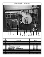
Страница 31: ...INCOMING PLUMBING ASSEMBLY 29 11 12 13 15 16 10 09 08 07 17 18 19 20 06 05 04 03 02 01 26 25 24 23 22 21 14 ...
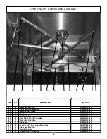
Страница 36: ...STEAM COIL ASSEMBLY 34 01 02 03 05 06 07 08 10 11 12 13 14 15 16 04 09 17 18 ...
Страница 41: ...Tempstar TGP ELECTRICAL DIAGRAM 208 240 VOLT 50 HERTZ 1 PHASE 39 ...


