


07610-004-29-29-D
10
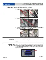
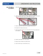
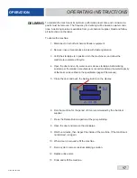
INSTRUCTIONS
INSTALLATION
Electrical and grounding conductors must comply with the applicable portions of the
National Electric Code ANSI/NFPA 70 (latest edition) and/or other electrical codes.
The data plate is located on the left side of the machine. Refer to the data plate for
machine operating requirements, machine voltage, total amperage, and serial number.
1. Open the control box by using a phillips screwdriver to remove the four screws
on the front cover.
2.
Install 3/4” conduit into the pre-punched holes in the back of the control box.
3. Route incoming-power wires, and connect to power block and grounding lug.
4.
Install the service wires (L3 for 3-Phase) to the appropriate terminals as they are
marked on the terminal block.
5. Install the grounding wire into the lug provided.
6. Tighten the connections.
“DE-OX” or similar anti-oxidation agent should be used on all power
connections
CAUTION!
Improperly connecting external devices can cause damage to the
machine and/or electrical infrastructure! Click
here
for a wiring guide
On 3-Phase machines only, correct pump motor rotation must be verified before
the machine is operated. Failure to do so can result in damage to the machine and
components.
1.
Follow the "Filling the Wash Tub" section.
2. Remove the left side panel of the machine.
3. Locate the wash pump motor and identify the arrow decal which shows the
correct motor rotation (if no decal is present, correct rotation is away from the
pump volute).
4.
Push the Delime Button on the display.
5. Observe the rotation of motor fan and quickly push the Delime Button again.
6. If rotation is incorrect, disconnect electrical power and reverse the L1 and L2
connections at terminal block shown in the section above.
ELECTRICAL POWER
CONNECTIONS
NOTICE
If necessary, see
"Heaters" page for
phase conversion kit.
GND
L1 L2 L3
3
Φ
Disconnect electrical
power supplies and
lockout/tagout in
accordance with
appropriate procedures
and codes at the
disconnect switch.
MOTOR ROTATION
i
CAUTION! On 3-Phase
machines only, correct
pump motor rotation
must be verified
before operation!
!
CAUTION
Imbalanced wild
leg goes to L3
NOTICE
Pump Volute
Motor Fan
Содержание Dynatemp Series
Страница 2: ......
Страница 37: ...07610 004 29 29 D 30 14 9 10 1 2 3 4 5 6 7 8 16 15 18 17 11 12 13 9 CANTILEVER ARM PARTS 3c 3d 3d 3a 3e 3b 19 ...
Страница 39: ...07610 004 29 29 D 32 11 10 9 12 13 19 20 4 18 17 16 14 15 1 2 3 5 6 7 8 21 TUB PARTS ...
Страница 41: ...07610 004 29 29 D 34 11 10 13 18 19 4 17 16 15 1 2 3 5 7 8 6 12 14 9 STEAM TUB PARTS ...
Страница 45: ...07610 004 29 29 D 38 PARTS WASH RINSE ARMS 1 2 3 4 5 6 7 8 9 10 11 ...
Страница 67: ......


