background image

32

ITEM

QTY

DESCRIPTION

PART NUMBER

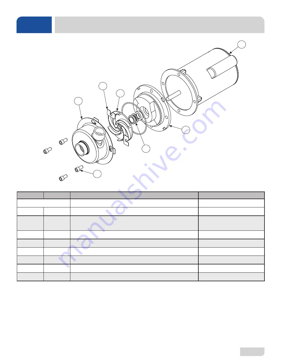
Complete Pump & Motor Assembly

06105-004-28-95

1

1

Motor Only

06105-004-32-03

2

1

Case O-Ring
Seal Plate

05330-002-81-83

05700-002-81-87

3

1

Mechanical Seal

05330-002-34-22 

4

4

Case Capscrew

05305-002-81-88

5

1

Pump Casing

05700-002-85-01

6

1

Shim Kit

05700-002-82-58

7

1

Impeller Assembly

05700-002-81-86

8

1

Drain Plug (Not Shown)

04730-002-81-89

1

7

2

6

5

3

4

MOTOR

PARTS

Содержание DELTA 5-E

Страница 1: ...DELTA 5 E INSTALLATION OPERATION AND SERVICE MANUAL Delta 5 E Manual 07610 003 37 08 L DELTA SERIES GLASSWASHER DISHMACHINES ...

Страница 2: ...lled by Jackson at the factory and are shipped with the Dishmachine carry only a 1 one year parts warranty Labor to repair or replace these components is not included in the warranty or covered by Jackson Booster heaters not manufactured by Jackson are not covered by this warranty but are warranted by their respective manufacturers This warranty is void if any defect or failure is a direct result ...

Страница 3: ...ROM DEFECTS IN MATERIALS AND WORKMANSHIP AND IS REPORTED TO JACKSON WITHIN 30 THIRTY DAYS FROM THE DATE OF INSTALLATION 9 DAMAGE CAUSED BY LABOR DISPUTE 10 DAMAGES RESULTING FROM IMPROPER CONNECTION TO UTILITY SERVICE 11 DAMAGES RESULTING FROM WATER CONDITIONS INADEQUATE OR EXCESSIVE WATER PRESSURE ACCIDENTS ALTERATIONS IMPROPER USE ABUSE HANDLING OVERLOADS TAMPERING IMPROPER INSTALLATION OR FAILU...

Страница 4: ...JH N A Removed Delta 5D and all references to it Changed P N 05330 100 01 10 to 05330 011 61 34 item 3 on pg 32 H 4 22 16 JH N A Changed drain connection information to 2 1 2 and changed NPT to No Hub Connection on pg 2 J 5 9 16 JH 8380 Changed Booster Tank Assembly view and applicable P Ns to show thermo stat change pg 32 Added schematic 09905 003 36 56 E to show thermostat change pg 37 Removed e...

Страница 5: ...r all of the dishmachines detailed in this manual We strongly recommend that you refer to this manual before making a call to our technical support staff Please have this manual open when you call so that our staff can refer you if necessary to the proper page Technical support is not available on holidays Contact technical support toll free at 1 888 800 5672 Technical support is available for ser...

Страница 6: ...e Regulator 6 Shock Absorber 6 Drain Line 6 Plumbing Check 6 Electrical Power Connections 7 Voltage Check 7 Surrounding Area 7 Temperature Setpoints 7 Chemical Feeder Equipment 8 Priming Chemical Feeder Pumps 8 OPERATION Operation Instructions 9 Preparation 9 Power Up 9 Initial Start up 9 Ware Preparation 11 Daily Start up 11 Washing a Rack of Ware 11 Operational Inspection 12 Shutdown Cleaning 12...

Страница 7: ...al Feeder Pump Components 21 Peri pump Box 22 Electrical Connection Box 23 Frame 24 Hood 25 Switch Panel 26 Tub 27 Frame Motor 30 Motor 32 Sustaining Heater 33 Inlet Plumbing 34 Plumbing Options 35 Solenoid Valve Repair Kits 36 Door 37 Front Panel 38 SCHEMATICS Delta 5 E 115 V 60 Hz 1 Phase 39 Delta 5 E Harness Connections 40 iv ...

Страница 8: ...Minimum Circuit Ampacity MOP Maximum Overcurrent Protection NFPA National Fire Protection Association NPT National Pipe Thread OD Outside Diameter PRV Pressure Regulating Valve PSI Pounds per Square Inch V Volts CAUTION WARNING NOTICE Risk of Injury to Personnel Risk of Damage to Equipment Risk of Electrical Shock Lockout Electrical Power Reference Data Plate Important Note i Caustic Chemicals Ins...

Страница 9: ...mm 6 3 4 171 mm 6 152 mm 12 1 4 311 mm 36 3 4 933 mm WITH DOOR OPEN 24 1 2 622 mm 25 1 4 641 mm 3 76 mm 11 1 2 292 mm CLEARANCE C A B LEGEND A Water Inlet 1 2 NPT B Drain Connection 2 NPT C Electrical Connection All dimensions from the floor can be increased 2 3 4 using the machine s adjustable feet C A B ...

Страница 10: ... Gallons 1 2 Water Temperatures F Minimum Wash Temperature 120 Minimum Rinse Temperature 120 140 F is recommended for both Other Water Requirements Water Line Size NPT 1 2 Drain Line Size NPT 2 Flow Pressure PSI 20 A 5 Minumum Chlorine Required PPM 50 Always refer to the machine data plate for specific electrical and water requirements The material provided on this page is for reference only and i...

Страница 11: ...only be performed by qualified electricians and authorized service agents Note that all electrical wiring used in the Delta series of machines must be rated at a minimum for 212 F 100 C and that only copper conductors must be used The Delta 5 E is designed so the wash motor is never running when the sustaining heater is on Total Amps is based on the higher of the two loads Delta 5 E Electrical Cha...

Страница 12: ... pair of pliers Verify the unit is level from front to back and side to side before making any electrical or plumbing connections The manufacturer does NOT endorse Tankless On demand water heaters for use with their machines The manufacturer DOES endorse and highly recommends the standard Tank style water heaters sized to properly handle the water heating requirements of the facility All plumbing ...

Страница 13: ... page to accommodate areas where water pressure fluctuates or is higher than the recommended pressure Take care not to confuse static pressure with flow pressure static pressure is line pressure in a no flow condition all valves and services are closed flow pressure is the pressure in the fill line when the valve is opened during the cycle It is suggested that the optional shock absorber see Plumb...

Страница 14: ...sponds with the voltage listed on the data plate If not contact a qualified service agency to examine the problem Do not run machine if voltage is too high or too low Shut off the service breaker and advise all proper personnel of the location of the breaker and any problems Replace the connection box lid and tighten down the screws This is a commercial machine and reaches temperatures that can ex...

Страница 15: ...Use prime switches located on the panel inside the door to prime each pump The switches are clearly marked with the type of chemical 3 To prime pumps hold the switch until the chemical can be observed entering the sump 4 Detergent is dispensed as required during the wash cycle by the timer The amount of detergent might need to be adjusted depending on water quality and type of detergent 5 Rinse ai...

Страница 16: ... as correct If not the voltage must be verified before energizing the unit Before the heater element can be energized the heater tank must be initially filled with water 1 Press and hold FILL button until water overflows into the wash strainer then release the button 2 The heater tank is now filled with water 3 Turn off the machine by pressing the ON OFF button INSTRUCTIONS OPERATION PREPARATION P...

Страница 17: ...er needs adjustment Use the following steps to adjust the fill time 1 Remove control box cover 2 Adjust the left side of CAM 4 To raise the water level increase open the notch of the CAM to lower the water level decrease close the notch of the CAM 3 Press and hold START button until the cycle starts about two seconds run a cycle then check the water level 4 Adjust as necessary then replace the con...

Страница 18: ...r during the cycle Presoak flatware in warm water to assist in removal of stuck on material Load plates and saucers in the same direction 1 Ensure items in the Preparation section have been verified 2 Verify chemical levels are correct 3 Ensure power is on and the tub has filled to the correct level 4 Push START button the unit will start run through the cycle and shut off automatically 5 Repeat t...

Страница 19: ...crew wash rinse arm from its manifold 5 Verify nozzles and arm are free from obstruction If clogged remove end caps clean nozzles with a brush and flush with fresh water 6 Replace end caps and tighten with screwdriver 7 Spray or wipe out interior of machine 8 Replace wash rinse arm 9 Ensure all strainers are clean and securely in place 10 Replace drain stopper 11 Use stainless steel polish to prot...

Страница 20: ...duce this occurence Treated water might not be suitable for use in other areas of operation and it might be necessary to install a water treatment system for the water going to the machine only Discuss this option with a qualified water treatment specialist Properly train operators on how much detergent is to be used per cycle Meet with a water treatment specialist and chemical supplier to discuss...

Страница 21: ...r overflows into the wash strainer 3 Add deliming solution per supplier s instructions 4 Close door 5 Flip NORMAL DELIME switch to DELIME 6 Run machine the period of time recommended by chemical supplier 7 Wait five minutes then inspect inside of the machine If the machine is not delimed run again 8 Flip NORMAL DELIME switch to NORMAL 9 Run two cycles to remove residual deliming solution DELIMING ...

Страница 22: ... To clean strainers wipe them out with a rag and rinse under a faucet A toothpick can be used to dislodge any stubborn debris Do not beat strainers on waste cans once bent they will not work properly If hard water is present install a water softener or SPS into the water line connecting to the machine see Plumbing section Ensure wash rinse arm is secure in the machine before operating Ensure the d...

Страница 23: ... or replace wires in motor 2 Verify delime switch triggers input on PLC If not check wiring replace membrane 3 Replace Motor operates on delime wash but not on automatic 1 Defective circuit in delime switch 2 Loose or broken wires 1 Replace switch 2 Tighten and or replace No water comes through the arm when the FILL switch is depressed 1 Water not turned on 2 Defective solenoid valve 1 Turn water ...

Страница 24: ...Replace 3 Adjust or replace thermostat 4 Replace heater element 5 Replace 6 Adjust 7 Replace Rinse water not at required temperature range 1 Check that white blue wires are connected 2 Defective thermometer 3 Defective thermostat 4 Incoming rinse water does not meet minimum criteria indicated on machine data plate 1 See Initial Start up section 2 Replace 3 Adjust or replace thermostat 4 Adjust as ...

Страница 25: ...8 9 10 1 3 2 4 11 27 11 27 12 13 28 14 15 5 6 Normal Delime 7 Rinse Aid Detergent 8 Sanitizer CONTROL BOX PARTS 1 9 10 5 6 7 8 2 3 11 27 11 27 4 14 15 12 13 28 Normal Delime Rinse aid Detergent Sanitizer ...

Страница 26: ...19 CONTROL BOX PARTS 18 27 17 28 17 28 16 27 19 29 32 31 30 21 20 24 27 25 26 27 27 22 23 17 28 18 27 17 28 16 27 24 27 25 26 27 27 22 23 32 29 19 30 31 20 21 ...

Страница 27: ...am Timer 09905 011 37 21 14 4 Fitting Conduit Heyco 1 2 05975 011 49 03 15 1 Fitting 1 2 Straight Snap in 05975 003 33 27 16 5 Clamp 5 8 Nylon 04730 011 39 01 17 2 Relay 2 Pole 05945 111 35 19 18 1 Terminal Board 05940 021 94 85 19 1 Harness Switch Panel 05700 003 35 37 20 1 Fitting 1 2 90 Degree Snap in 05975 003 33 28 21 1 Conduit 1 2 x 40 05700 003 35 48 22 1 Cycle Counter 05990 111 35 38 23 2 ...

Страница 28: ...or 14 RPM 115 V Rinse aid Feeder Pump 04320 111 35 13 1 Motor 36 RPM 115 V Detergent Sanitizer Feeder Pump 04320 111 35 14 3 2 Screw 8 32 x 1 2 Phillips Flat Head 05305 011 37 06 4 1 Tube 3 16 x 8 Clear Tygoprene 05700 003 22 89 5 1 Roller Purple Dot 04320 004 59 43 6 4 Screw 6 32 x 3 4 Phillips Pan Head 05305 011 37 05 7 1 Cover Clear 04320 004 59 45 8 4 Screw 8 32 x 3 8 Flat Head 05305 011 37 07...

Страница 29: ...x 04730 011 39 01 8 1 Clamp 1 Nylon 04730 002 41 88 9 5 Screw 10 32 x 1 2 05305 011 39 36 10 3 Locknut 10 24 SS Hex w Nylon Insert 05310 373 01 00 11 3 Tube Stiffener Not Shown 05700 002 66 49 12 1 Tubing 1 4 OD x 60 Long Blue 05700 002 52 34 13 1 Tubing 1 4 OD x 60 Long White 05700 002 52 33 14 1 Tubing 1 4 OD x 60 Long Red 05700 011 63 18 15 1 Terminal Board Not Shown 05940 001 97 91 16 1 Tubing...

Страница 30: ...0 500 09 61 4 1 Locknut 6 32 with Nylon Insert 05310 373 03 00 5 5 Locknut 10 24 with Nylon Insert 05310 373 01 00 6 1 Lug Ground 05940 200 76 00 7 1 Decal Power Connection 09905 011 47 64 8 1 Decal Warning to Disconnect Power 09905 004 08 16 9 1 Screw 10 32 x 1 2 Long Phillips Trusshead 05305 011 39 36 10 2 Decal Copper Conductors Only 09905 011 47 35 11 1 Cover Solenoid Box 05700 003 46 72 10 11...

Страница 31: ...40 6 1 Clamp Pipe 05700 000 35 05 7 8 Washer 1 4 20 SS 05311 174 01 00 8 1 Keeper Door Panel Latch 05700 003 09 31 9 4 Locknut 1 4 20 SS Hex with Nylon Insert 05310 374 01 00 10 5 Nut Hex 1 4 20 05310 274 01 00 11 1 Heater Mounting Plate Weldment 05700 002 51 93 12 1 Bracket Temperature Gauge 05700 003 14 53 13 1 Bolt 1 4 20 x 1 2 05305 274 02 00 14 1 Bracket Manifold Position Tube 05700 011 34 63...

Страница 32: ...tch 115 V Reed 05930 002 36 80 3 1 Bracket Limit Switch 05700 021 71 18 4 4 Locknut 10 24 with Nylon Insert 05310 373 01 00 5 2 Clamp Pipe 5 8 05700 000 35 06 6 2 Rack Rail Weldment 05700 002 45 67 7 2 Washer 1 4 20 I D 05311 174 01 00 8 1 Gasket Side Panel 05330 100 10 00 1 8 5 6 4 7 2 3 ...

Страница 33: ...3 14 91 3 1 Switch On Off Assembly 05700 003 14 92 4 1 Light Amber 05945 504 06 18 5 1 Light Red 05945 504 07 18 6 1 Decal Switch Panel 09905 003 08 63 7 1 Fitting 25 546 05975 011 65 51 8 3 Plug 3 4 Hole 04730 011 60 21 9 6 Locknut 10 24 with Nylon Insert 05310 373 01 00 10 6 Washer 05311 176 02 00 11 1 Terminal Board Not Shown 05940 001 97 91 1 2 3 4 8 5 9 6 7 10 8 9 10 2 ...

Страница 34: ...7 14c 14b 14a 27b 27a 16b 16a 30d 30e 30c 30b 30a 17b 17a 17c TUB PARTS 1 9 5 6 7 8 2 3 11 4 14 15 12 13 27 18 23 24 25 22 22 19 29 20 21 14a 17a 17b 17c 26a 26b 29a 29b 29c 29d 29e 3 24 7 24 16 17 26 10 ...

Страница 35: ... Wash Arm Assembly 05700 021 39 23 14a 1 Wash Arm End cap 05700 003 31 59 15 1 Sump Strainer 05700 002 60 50 16 1 Stand Pipe 05700 004 19 50 17 1 Complete Drain Link Assembly 05700 002 45 52 17a 1 Drain Link 05700 002 40 83 17b 1 Nut Hex 5 16 18 05310 275 01 00 17c 1 Drain Link Connector 05700 002 38 10 18 1 Hair Pin 1 8 to 1 05315 011 60 09 19 1 Fill Tube Weldment 05700 002 45 61 20 18 Washer 1 4...

Страница 36: ...41 88 29 1 Drain Solenoid Box Assembly 05700 003 09 61 29a 1 Solenoid Box Weldment 05700 003 35 88 29b 1 Drain Solenoid 115 V 04810 200 11 00 29c 4 Locknut 10 24 with Nylon Insert 05310 373 01 00 29d 1 Decal Warning to Disconnect Power 09905 004 08 16 29e 1 Solenoid Box Cover 05700 003 30 25 TUB PARTS ...

Страница 37: ...30 FRAME MOTOR PARTS See Frame Page 5 6 8 9 7 13 4 11 1 10 11 2 11 3a 3b See Sustaining Heater Page See Motor Page See Inlet Plumbing Page 12 3 ...

Страница 38: ...2 05700 002 45 59 4 1 Wash Restrictor 05700 002 84 69 5 1 Accumulator Strainer Weldment 05700 003 33 25 6 1 Accumulator Weldment 05700 002 51 95 7 8 Bolt 1 4 20 x 1 2 05305 274 02 00 8 18 Locknut 1 4 20 SS Hex with Nylon Insert 05310 374 01 00 9 18 Washer 1 4 20 SS 05311 174 01 00 10 1 Hose Clamp 13 16 to 1 1 2 04730 719 06 09 11 3 Hose Clamp 1 1 16 to 2 1 4 04730 719 18 00 12 1 Close Nipple 1 2 B...

Страница 39: ...004 32 03 2 1 Case O Ring Seal Plate 05330 002 81 83 05700 002 81 87 3 1 Mechanical Seal 05330 002 34 22 4 4 Case Capscrew 05305 002 81 88 5 1 Pump Casing 05700 002 85 01 6 1 Shim Kit 05700 002 82 58 7 1 Impeller Assembly 05700 002 81 86 8 1 Drain Plug Not Shown 04730 002 81 89 1 7 2 6 5 3 4 MOTOR PARTS ...
Страница 40: ...18 05310 275 01 00 6 2 Nut Lock 6 32 Hex with Nylon Insert 05310 373 03 00 7 2 Spacer 1 4 OD x 9 32 09330 004 34 91 8 1 Thermostat Elan Electric Dual 06685 004 17 27 9 1 Cover Heater Box 05700 004 34 90 10 1 Decal Warning to Disconnect Power 09905 004 08 16 11 1 Probe Thermistor 06685 004 17 26 12 1 Probe Fitting Thermostat 05310 924 02 05 13 1 Washer Thermostat Probe Fitting 05700 001 23 96 1 7 2...

Страница 41: ...207 15 00 3 1 Valve Solenoid 1 2 NPT 115 V 04810 100 12 18 4 1 Adaptor 1 2 Fitting CU to Male 04730 401 03 01 5 2 Tube Copper 1 2 x 1 1 4 05700 001 08 28 6 1 Union 1 2 04730 412 05 01 7 1 Elbow 1 2 04730 406 01 01 8 1 Tube Copper 1 2 x 4 1 4 05700 001 01 60 9 1 Elbow 90 Degree CU to MSPS 04730 406 32 01 9 1 3 4 5 6 7 8 9 2 5 ...

Страница 42: ...nger O ring 06401 003 06 23 Replacement Cartridge inspect at least every 6 months 04730 003 28 04 SPS System 04730 003 28 03 Replacement Test Strip Not Shown 06401 003 28 06 Must be installed vertically The provided bracket is secured to the wall Observe proper inlet outlet water directions flow directions are molded into the top of the head Line pressure should be released before changing cartrid...

Страница 43: ...embly 1 2 04810 100 09 18 Water H Water Hammer Arrestor 1 2 NPT 06685 100 05 00 Complete Vacu Data Plate Cap Retainer Components of Repair Kit 06401 003 06 23 Screw Data Plate Coil and Housing Valve Bonnet Spring position is moved for clarity Goes below the plunger Valve Body Mesh Screen Screen Retainer Diaphragm Retainer Spring Plunger Kit 06401 003 07 40 O Ring Diaphragm 06401 003 07 41 ...

Страница 44: ... Reed Switch 05930 002 88 42 1 Magnet Cover not shown 05700 004 07 38 3 1 Locknut 6 32 SS Hex with Nylon Insert 05310 373 03 00 4 1 Locknut 1 4 20 SS Hex with Nylon Insert 05310 374 01 00 5 2 Nut Hex 1 4 20 SS 05310 274 01 00 6 1 Bolt 1 4 20 Eye SS 05306 002 55 59 7 1 Spring Door 05340 011 44 58 DOOR PARTS 1 3 4 7 5 6 2 ...

Страница 45: ...38 FRONT PANEL PARTS ITEM QTY DESCRIPTION PART NUMBER Complete Panel Assembly 05700 003 09 53 1 1 Panel Weldment 05700 003 09 54 2 1 Handle 05340 001 96 30 1 2 ...

Страница 46: ...39 DELTA 5 E 115 V 60 HZ 1 PHASE SCHEMATICS ...

Страница 47: ...40 Probe SUSTAINING HEATER DELTA 5 E HARNESS CONNECTIONS SCHEMATICS ...

Страница 48: ...41 Jackson WWS Inc 6209 N US Hwy 25E Gray KY 40734 USA 1 888 800 5672 www jacksonwws com Delta 5 E Manual 07610 003 37 08 L ...

Отзывы: