background image

cause severe engine damage. Not all cars need
this modification.
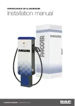
3.4 NON POWER STEERING CARS: Locate
your lower bracket assembly from the kit. The
end with the small 90-degree bracket mounts to
the idler bracket (standard on AC equipped cars)
or to new idler bracket (supplied with kit for non-
AC, non-PS cars). Use the new, longer 10mm
bolt provided to attach this bracket to the engine
(Review figure 3.4 for bolt location).

4.0 POWERCARD

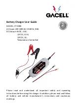
4.1 To access the ECU, remove the passenger’s
side kick panel trim by removing the plastic fas-
tener securing the top, front portion of the panel.
Use a small screwdriver to pull out the center
section and then pull the whole fastener out.
There is also a push in fastener in the center of
the panel. Slip your fingers up behind the panel
and gently pull out on the center until it pops
free. Once the center fastener is free, slide the
panel out from under the door sill trim and set it
aside. Remove the forward two screws from the
door sill trim to allow easy removal and reinstal-
lation of the carpet. Remove the floor mat and
pull back the carpet to expose a large metal
plate. Using a 10mm socket, remove the four
nuts and one bolt that secure the plate to the car.
Remove the plate to gain access to the
Electronic Control Unit (ECU). Illustration 4.1

4.2 Locate the PowerCard (Fuel Management
System) from your kit. We have included enough
wire to mount it on the center console or in the
glove box (recommended) and still reach the
passenger’s side footwell where the ECU is
located. Decide where you want to mount it,
route the wires from that location to the console
(or thru the glovebox area) back behind the
dashboard and down into the passenger’s side
footwell. Then cut the extra wire to length or
loop and wrap it with tape. Strip 1/4” of insulation
off of each of the PowerCard’s wires. Gather
together one (1) female spade connectors and
five (5) male spade connectors. Crimp the
female spade connector onto the Purple wire

and then crimp the male spade connectors onto
the rest of the wires. Slip the wires into the
included split loom. The split loom can be cut to
length as necessary. The Powercard will connect
to the ECU harness in the passenger (right hand)
foot well. We recommend routing the wires under
the dash or behind the center console on their
way to the footwell to keep them out of the dri-
ver’s way. 

Supercharger Installation Instructions

999-156, 999-157, 999-158 & 999-159

-6-

Revised 06/08

Illustration 4.2

Содержание Automobile Battery Charger

Страница 1: ...e not a competent mechanic do not attempt this installa tion TOOLS REQUIRED Most of these tools are available at your local hardware or auto parts stores 17mm 14mm 13mm 12mm 10mm 8mm sockets Deep sock...

Страница 2: ...ll restrictor inside the rubber hose that ran from the cam cover to the chrome tubing It can be felt as a lump in the straight section of the hose near the chrome tube end Persuade it out by gently cl...

Страница 3: ...same position as the standard throttle body on the intake manifold Use the 1104 sealant provided if the original gasket was not salvaged Reconnect the coolant hoses to the idle control valve as you f...

Страница 4: ...en the bottom bolt to 36 ft lbs Once the bot tom bolt is tight remove the upper bolt Now slide the power steering pivot bolt rearward out of the pump It will be reinstalled from the front Remove the r...

Страница 5: ...Now tighten the hose on the power steering pump Once the two bolts are tight the two tabs on the power steering hose clamp can be bent down again Illustration 3 3 VERY IMPORTANT Check the clearance be...

Страница 6: ...ocket remove the four nuts and one bolt that secure the plate to the car Remove the plate to gain access to the Electronic Control Unit ECU Illustration 4 1 4 2 Locate the PowerCard Fuel Management Sy...

Страница 7: ...connector onto the side of the cut wire that leads into the harness Crimp a Female Spade connector onto the side of the cut wire that leads to the ECU connector Connect the Powercard s Red wire to the...

Страница 8: ...t get stretched or pinched in any of the glovebox hinges The split loom plastic sheathing from Step 4 1 will help keep the wires located properly For a dashboard mount you can put Velcro on the back...

Страница 9: ...o the elbow 6 0 SUPERCHARGER INSTALLATION 6 1 Remove the engine lift eyelet at the front of the engine just above the exhaust manifold by removing the bolt using a 14mm socket Using the two new flange...

Страница 10: ...ool Make sure that the cable runs in the center of the groove of the throttle spool If it does not adjust the throttle cable bracket left or right until it is centered in the spool s groove Have an as...

Страница 11: ...it along its length to cover the brake line running just above the elbow This will prevent any contact at this point which may result in noise during opera tion 7 5 Locate the 3 4 diameter idle air ho...

Страница 12: ...allow for engine movement Make sure the line is not pinched in any way and that it has no possibility of interfering with the throttle cable or spool Use tie wraps as necessary to secure the line The...

Страница 13: ...h Complete step 8 5 before starting your engine 8 5 CLEARANCES IMPORTANT MAKE SURE THAT YOU HAVE AT LEAST 3 4 INCH CLEARANCE BETWEEN ANY ENGINE MOUNTED COMPONENT AND ANY BODY MOUNTED COMPONENT CRITICA...

Страница 14: ...see the silver spade connector through the translucent insu lation then you need to disconnect and properly reconnect this connection 9 2 IDLE ADJUSTMENT Restart your engine Using the idle airscrew on...

Страница 15: ...the position that bypasses the boost air back into the supercharger inlet As you blip the throttle the actuator arm will move and close a butterfly valve inside the bypass manifold Using a short piece...

Страница 16: ...or arm contact point and shaft bushing with light grease to insure long life these parts are exposed to under hood dirt and grime TROUBLESHOOTING SYMPTOM Engine cranks but will not start PROBABLE CAUS...

Страница 17: ...and Yellow Black Injectors T Tap these wires White Yellow Green Gray PowerCard wires Ground T Tap this wire ECU Red Blue Exhaust O2 Sensor Cut this wire and splice in PowerCard In Out Purple Purple Ye...

Отзывы: