Engine Overhaul Manual
Jabiru Aircraft
Pty Ltd
Jabiru 2200 & 3300 Aircraft Engines
This document is controlled while it remains on the Jabiru server. Once this no longer applies the document becomes uncontrolled.
ISSUE
1
2
3
4
5
6 7
Dated : 28/10/2014
Issued By: AS
Page: 60 of 201
L:\files\Manuals_For_Products\Engine_Manuals\Overhaul_Manual\JEM0001-7_Overhaul_Manual_DRAFT_(29_10_14).docx
5.9.1.4
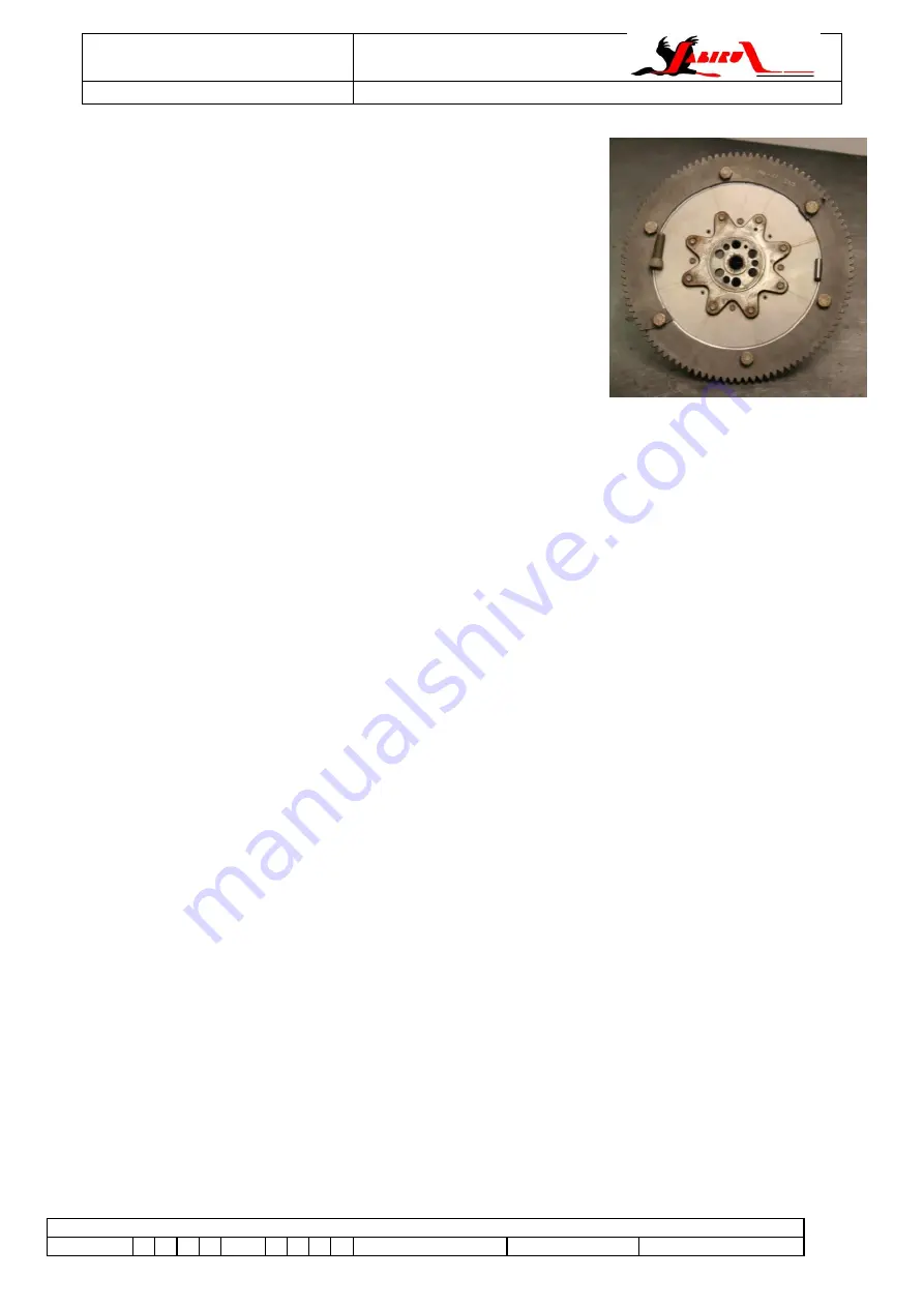
Optional Updates: Starfish Flywheel Adaptor
Figure 64
– Starfish Flywheel
5.9.1.5
Cleaning
Clean away all paint from the front of the crankshaft and the propeller flange.
Clean out all threaded holes in the ends of the crankshaft with a 5/16” or 3/8” UNF tap as appropriate
then wash and blow out all debris from the holes.
Wash the crankshaft thoroughly with kerosene, taking care to remove all of the sludge from the inside of
the front main bearing: careful use of a small scraper will aid sludge removal. Individually clean each
main to big end oil way drilling using a small brush or similar.
Blow out all of the oil ways, dry the crankshaft and coat with engine oil or other corrosion preventative.
5.9.1.6
Inspection
Inspect the internal face of the propeller flange where the screw heads & washers will seat when
assembled. Ensure this surface is clean of all paint and retaining compound.
The crankshaft and propeller flange must now be checked for straightness: lay the crankshaft between
vee blocks and use a dial indicator on a magnetic base to check that the runout as measured at the
very front of the crankshaft is within the range 0.01 to 0.05mm. Upper limits for crank run-out are given
in Table 10.
Now mount the propeller flange onto the crankshaft with 3 cap screws and position the crankshaft so
that all end float is negated then check the propeller flange for straightness at the outer face of the
flange with the dial gauge.
Typical flange run-out should be in the range of 0.02 - 0.06mm. Upper limits are given in Table 10.
Run-out exceeding these limits would indicate the requirement for a new propeller flange, assuming that
the crankshaft is within tolerance.
Note that this measurement can also be carried out with the crank fitted into a crankcase
– provided
that the case is fitted with the front, rear and thrust bearings.
Measure the main and big end journals with a micrometer. The main bearing and big end journals must
measure in the limits given in Table 10. Earlier cranks are 47.918 to 47.938 while later parts are 47.930
to 47.950. Ultimately the clearance between crank and bearings determines if a crank can be re-used.
This must be checked before deciding if a replacement is necessary or not
– acceptable clearances are
given in Table 12.
Current engines use a steel adaptor between the crankshaft and
the flywheel, calle
d a “starfish” because of its shape (shown in
Figure 64). While not mandatory it is strongly recommended that at
overhaul engines are updated to this arrangement. The aluminium
flywheel and alternator rotor are among the parts required for the
update
– contact Jabiru Aircraft for details.


