background image

3

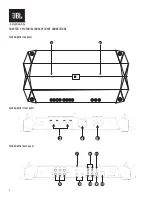
1. Power indicator: 

The light will illuminate in white when the amp is receiving power and playing. 

2. Protect indicator: 

The indicator will illuminate in red if the amp enters Protect mode in the event of conditions such as over/under voltage, short circuit, amplifier 

output circuit failure, or excessive heat.

3. Speaker Output Connectors: 

•  Connect the speakers to these terminals, observing proper polarity (connect each speaker’s positive (+) lead to the appropriate positive 

(+) terminal, and negative (-) lead to the appropriate negative (-) terminal.

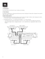
•  The Club-704 features Front L+, L-, R+, and R- terminals, and Rear L+, L-, R+, and R- terminals.

 °  4-channel operation: Connect the front left speaker to the Front L+ and L- terminals, and the front right speaker to the Front R+ 

and R- terminals. Connect the rear left speaker to the Rear L+ and L- terminals, and the rear right speaker to the Rear R+ and R- 
terminals.

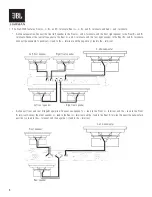
Left Front speaker

Right Front speaker

Left rear speaker

Right rear speaker

Содержание Club-4505

Страница 1: ...EN OWNER S MANUAL JBL Club 704 Club 4505 Club 5501 AMPLIFIERS ...

Страница 2: ...ortant documents in order to expedite warranty service if needed ABOUTTHE MANUAL This manual describes general installation guidelines and operation instructions However please note that proper installation of mobile audio and video components requires qualified experience with mechanical and electrical procedures If you do not have the knowledge and tools to successfully perform this installation...

Страница 3: ...03 3 Speaker output connectors 03 4 Fuses 06 5 Power input connectors 06 6 Front and rear inputs and outputs RCA 07 7 Input level 08 8 Crossover filter selectors 08 9 Gain 08 10 Crossover frequency controls 08 11 HALOsonic input 08 12 ADAS Assign Club 704 and Club 4505 09 13 ADAS Input Club 704 and Club 4505 09 CHAPTER 3 OPERATIONS 10 CHAPTER 4 TROUBLESHOOTING 11 CHAPTER 5 SPECIFICATIONS 12 ...

Страница 4: ...1 CHAPTER 1 PICTORIAL INDEX OF INPUT CONNECTIONS Club Amplifier top panel Club Amplifier front panel Club Amplifier back panel POWER PROTECT 1 2 3 4 5 8 10 12 13 11 9 7 6 ...

Страница 5: ...secure and properly insulated If you must replace any of the amplifier s fuses use the same type of fuse and current rating as the original To keep the amplifier cool choose a location that provides enough air circulation such as under a seat or in the trunk Do not mount the amplifier with the heat sink facing downward as this interferes with cooling Mount the amplifier so that it will not be dama...

Страница 6: ...ls observing proper polarity connect each speaker s positive lead to the appropriate positive terminal and negative lead to the appropriate negative terminal The Club 704 features Front L L R and R terminals and Rear L L R and R terminals 4 channel operation Connect the front left speaker to the Front L and L terminals and the front right speaker to the Front R and R terminals Connect the rear lef...

Страница 7: ...ear L terminal and the lead to the Rear R terminal 2 channel bridged operation Connect one speaker s lead to the Front L terminal and the lead to the Front R terminal Connect the other speaker s lead to the Rear L terminal and the lead to the Rear R terminal Right Front speaker Left Front speaker 4 ohm subwoofer 4 ohm subwoofer 4 ohm subwoofer ...

Страница 8: ...terminals Connect the subwoofer s positive lead to the terminal and the negative lead to the terminal 3 channel front and rear bridged operation Connect one speaker s lead to the Front L terminal and the lead to the Front R terminal Connect the other speaker s lead to the Rear L terminal and the lead to the Rear R terminal Connect the subwoofer s positive lead to the terminal and the negative lead...

Страница 9: ...er impedance for bridged operation is 4ohms 4 Fuses Replace only with fuses of the same amperage Club 704 Club 5501 30A Club 4505 30A 5 Power Input Connectors Power Run power wire from the 12V input to the positive terminal of the vehicle s battery Install an appropriate fuse holder and fuse 60A minimum on Club 704 and Club 5501 105A minimum on Club 4505 within 18 457mm of the battery Make sure th...

Страница 10: ...CA If your source unit offers preamp outputs connect to the FRONT REAR and or SUB inputs using RCA patch cables To connect a second amp directly to the Club 704 amplifier run a patch cable from the PRE OUT outputs to the second amp s preamp inputs If your car audio system s head unit does not have line level outputs Use the supplied bare wire to RCA adapters to connect the Club amplifier s inputs ...

Страница 11: ... Input Level switch set in the HI1 position Note If you have connected your Club amplifier to a factory audio system s speaker outputs the audio signal may fail to play If this happens change the Input Level switch to the HI2 position The HI2 position includes a circuit designed to fool this type of factory audio system into seeing a speaker connected to its input Important The HI2 setting should ...

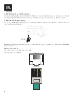
Страница 12: ...t and RR for the rear right 13 ADAS INPUT Club 704 and Club 4505 only Lets you plug a T568B cable sold separately from an optional Advanced Driver Assistance System into the amp s RJ45 input jack Also functions as a priority switching input When the system issues a warning or message the amp will mute the music and play it over the speaker you ve selected with the ADAS ASSIGN dial see 12 previous ...

Страница 13: ...s setting if you are connecting a subwoofer s or want to provide a low pass filter for separate mid bass speakers FULL Full range Choose this setting if you are connecting full range speakers and are not using a subwoofer in your system HP High pass Choose this setting to prevent low bass from reaching midrange or full range speakers when you are using a subwoofer in your system Step 2 Use crossov...

Страница 14: ... and POWER INDICATORS flash CAUSE and SOLUTION Voltage less than 9V on BATT connection Check vehicle charging system PROBLEM Distorted audio CAUSE and SOLUTION Gain is not set properly Check INPUT LEVEL setting Check speaker wires for shorts or grounds Amplifier or source unit may be defective PROBLEM Distorted audio and PROTECT INDICATOR flashes CAUSE and SOLUTION Short circuit in speaker or wire...

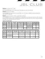
Страница 15: ...nd is one of the main causes for extraneous noise in your audio system CHAPTER 5 SPECIFICATIONS Model RMS power 4 ohms RMS power 2 ohms RMS bridged power 4 ohms Total peak power Frequency response Maximum signal input Maximum sensitivity Club 704 70W x 4 100W x 4 200W x 2 1000W 10Hz 40kHz 20V 200mV Club 4505 45W x 4 65W x 4 130 x 2 1800W 10Hz 40kHz full range 20V 200mV 320W x 1 500W x 1 10Hz 320Hz...

Страница 16: ...mark and logos are registered trademarks owned by Bluetooth SIG Inc and any use of such marks by HARMAN International Industries Incorporated is under license Other trademarks and trade names are those of their respective owners Features specifications and appearance are subject to change without notice HARMAN International Industries Inc 8500 Balboa Boulevard Northridge CA 91329 USA www infinitys...

Отзывы: