background image

4.External Control

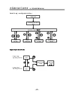
  4.2 Quick Reference

S/S

EXT

EHE Quick reference Guide

=Start/Stop key

=EXT[ternal]key

From:

Press

To

WAIT

S/S

run in manual mode

decrease frequency (360 to 1 spm )

increase frequency (1 to 360 spm )

EXT

run 

EXT

EXT

+

SET

  external mode

EXT

+

SET

  external values

Run manual

decrease frequency (360 to 1 spm )

increase frequency (1 to 360 spm )

S/S

return to


WAIT

Run 

EXT

S/S

return to


WAIT

SET

 external mode

select 

DIG

 (multiply or divide )

select 

ANA

 ( milliamp input )

S/S

accept data and return to 

WAIT

SET

 external values

DIG

EXT

select / (divide) or X (multiply)

increase value (1 to 999 )

decrease value (999 to 1 )

S/S

accept data and return to 

WAIT

ANA

or

select 

4-20,20-0,20-4, 

or

 0-20

S/S

accept data and return to 

WAIT

- 22 -

Содержание EH-E

Страница 1: ...IWAKI Electromagnetic Metering Pump Instruction Manual EH E Type Read this manual before use of product...

Страница 2: ...Unpacking 6 2 Operation Principle 6 3 Specifications 7 4 Dimensions 10 2 INSTALLATION 14 1 Before Use 15 2 Location 16 3 Supply Tubing 16 4 Discharge Tubing 17 5 Electrical 17 3 OPERATION 18 1 Primin...

Страница 3: ...or misapplication of the contents of the Warning section could lead to a serious accident including death or injury Caution Nonobservance or misapplication of the contents of the Caution section coul...

Страница 4: ...n accordance with the pump specifications and application range Prohibited No remodeling Never remodel a pump Otherwise a serious accident may result Iwaki will not be responsible for any accident or...

Страница 5: ...n If an electric part or wiring gets wet with the liquid spilled over accidentally a fire or electrical shock may be caused Install the system in a place free from liquid spillage or leakage Do not we...

Страница 6: ...ndle the power cable carefully Electrical Shock Follow the instruction manual Replace the consumable part by following the descriptions in the instruction manual Do not disassemble any part of the pum...

Страница 7: ...1 INTRODUCTION 1 Unpacking 6 2 Operation Principle 6 3 Specifications 7 4 Specifications of Control Unit 9 5 Dimensions 10 5...

Страница 8: ...id When the solenoid coil is energized by the control unit the armature shaft moves forward due to the magnetic force of the solenoid The shaft is attached to a PTFE faced diaphragm which is part of t...

Страница 9: ...onded to EPDM PTFE PVC Polyvinyl chloride Transparent GFRPP Glass fiber reinforced polypropylene M PVC Polyvinyl chloride Machined CE Alumina ceramics SUS316 316 Stainless steel FKM Fluoroelastomer EP...

Страница 10: ...110V AC115V AC200V AC220V AC230V AC240V AC230V AC 90 126V AC 90 126V AC180 220V AC198 264V AC207 253V 50 60 Hz Lead wire P with plug No symbol without plug Controller E Special configuration 0 99 Poin...

Страница 11: ...SH type install air chamber of approx 500 ml volume at the location as close to pump discharge port Adjustment Range Recommended stroke length adjustment range 20 to 100 Recommended frequency adjustme...

Страница 12: ...5 Dimensions Material symbol VC V6 PC VM FC 10...

Страница 13: ...5 Dimensions Material symbol VC V6 PC VM FC 11...

Страница 14: ...5 Dimensions Material symbol SH 12...

Страница 15: ...5 Dimensions Material symbol SH 13...

Страница 16: ...2 INSTALLATION 1 Before Use 15 2 Location 16 3 Suction tubing 16 4 Discharge tubing 17 5 Electrical 17 14...

Страница 17: ...start it from the beginning again Specified power only Do not operate the pump on voltage which is not specified on the name plate Failure to do so may result in damage or fire Only the specified powe...

Страница 18: ...ks well See Figure 2 The supply tank or cover can also be used if it has provisions for mounting a pump See Figure 3 In any care the total suction lift should not exceed 1 5m 3 Supply tubing The suppl...

Страница 19: ...tubing from sharp edges that could chafe or cut it If applicable install the injection valve at the injection point and connect the tubing to the injection valve 5 Electrical Connect the pump power c...

Страница 20: ...Priming 19 2 Adjustment 20 3 Calibration 20 4 External Control 4 1 Display Keypad and Wiring Overview 21 4 2 Quick Reference 22 4 3 Digital Mode 23 4 4 Analog Mode STOP Function 24 4 5 AC Power Interr...

Страница 21: ...kage may result Fasten the 4 hex socket bolts tightly before starting the initial pump operation The bolts may be loosened during storage or transportation of the pump depending upon the condition Fas...

Страница 22: ...tputs are required it will be necessary to also reduce the stroke length Minimum recommended stroke length is 20 3 Calibration If exact output calibration is required first prime and adjust the pump a...

Страница 23: ...ump is in standby mode EXT indicator Visible when pump is operating via external input STOP indicator Visible when the pump is stopped via external signal The pump stops pumping UP key Increases numer...

Страница 24: ...rnal values Run manual decrease frequency 360 to 1 spm increase frequency 1 to 360 spm S S return to WAIT Run EXT S S return to WAIT SET external mode select DIG multiply or divide select ANA milliamp...

Страница 25: ...start start start start start stop stop stop stop stop Run Run Set External Set External Manual External Mode Values Signal Operation Mode Signal Operation Mode Signal Operation Mode Signal Operation...

Страница 26: ...ration 1 999 Divide operation 1 999 Multiply start operation X stop EXT EXT Set External Stand by Values mode WAIT Divide operation start Set value stop Signal Setting Mode Analog Input Operating Func...

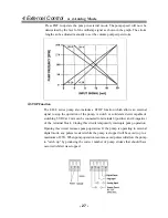
Страница 27: ...the value or will increase or decrease the m1ultiplier or divider Pressing a button once will change the value by one Holding a button down will continuously increment or decrement the value slowly at...

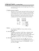
Страница 28: ...from conductors and connect the positive side to terminal 5 and the negative side to terminal 8 2 Settings Start with pump in the WAITstate If it is not currently in wait press START STOP once 3 1 Se...

Страница 29: ...eration of the pump A switch or solid state device capable of switching 5 VDC at 2 mA can be connected to terminals 6 positive and 8 negative of the terminal block Closing this circuit temporarily int...

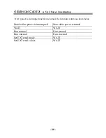
Страница 30: ...AC power is interrupted and then returned the functions return as shown below State before power is interrupted State after power returned WAIT WAIT Run manual Run manual Run external Run external Set...

Страница 31: ...4 Maintenance 1 Maintenance 30 2 Diaphragm Replacement 30 3 Valve Replacement 30 4 Tubing 30 5 Names of Part and Structure 31 29...

Страница 32: ...ad bolts to a torque of 2 6 N m 3 Valve Replacement Remove the suction and discharge tubing Remove the suction fitting two valve cartridges o ring and gasket s Install the new o ring gasket s and valv...

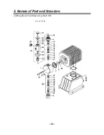
Страница 33: ...5 Names of Part and Structure 1 Pump Head Unit Material symbol VC V6 PC P6 VM FC 31...

Страница 34: ...5 Names of Part and Structure 2 Pump Head Unit Material symbol SH E30 E35 E45 32...

Страница 35: ...5 Names of Part and Structure 3 Pump Head Unit Material symbol SH E55 33...

Страница 36: ...t 12 Valve seat 13 Valve ball 13 Valve ball 14 Valve gasket 14 Valve gasket 18 Diaphragm spacer 17 O ring Gasket for type FC 19 Hex sock cap bolt 18 Diaphragm spacer 20 Plain washer 19 Hex sock cap bo...

Страница 37: ...5 Troubleshooting 1 Troubleshooting 36 35...

Страница 38: ...is missing Install valve gasket Valve set assembly direction is wrong Reassemble valve set Pump is air locked Prime pump per instructions Suction or discharge valve is clogged with foreign matter Dis...

Страница 39: ...IWAKI CO LTD 6 6 Kanada sudacho 2 chome Chiyoda ku Tokyo 101 8558 Japan Tel 81 3 3254 2935 Fax 81 3 3252 8892 T308 1 99 2...

Отзывы: