


42
insTAllATiOn direcTiVe
N45 MNA M10
N67 MNA M15
MAY 2006
N45 MNA M10.01
N67 MNA M15.01
*"
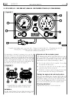
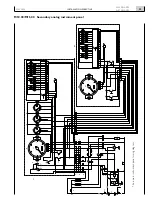
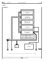
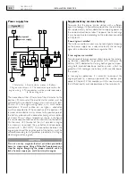
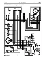
Synoptic
Figure 2
indicATiOns And AlArMs
sensOrs
enGine sTOP
sOlenOid VAlVe
eMerGency sTOP
BUTTOn (OPT)
AlTernATOr
elecTric sTArTer
MOTOr
BATTery
06_011_N
rl1
3
1
2
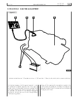
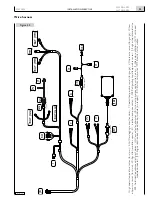
1. Connector for instrument panel connection wire harness - 2. Engine wire harness - 3. Power line.
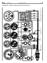
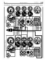
The wire harnesses provided with the engine include the
connectors for all optional components which may ordered
and their connections to the JB connector for the indicator
and control panel.
Содержание N45 MNA M10
Страница 23: ...INSTALLATION DIRECTIVE 23 MAY 2006 N45 MNA M10 N67 MNA M15 ...
Страница 63: ...63 INSTALLATION DIRECTIVE N45 MNA M10 N67 MNA M15 MAY 2006 COMMON CHAPTERS ...
Страница 70: ...70 INSTALLATION DIRECTIVE N45 MNA M10 N67 MNA M15 MAY 2006 ...
Страница 71: ...71 INSTALLATION DIRECTIVE N45 MNA M10 N67 MNA M15 MAY 2006 Page 27 APPENDIX REMOTE OIL FILTERS 72 ...
Страница 73: ......