S-7
ATEX CONSIDERATIONS and INTENDED USE
Special care must be taken in potentially explosive environments to ensure that the equipment is properly
maintained. This includes but is not limited to:
1. Monitoring the pump frame and liquid end temperature.
2. Maintaining proper bearing lubrication.
3. Ensuring that the pump is operated in the intended hydraulic range.
The ATEX conformance is only applicable when the pump unit is operated within its intended use. Operating,
installing or maintaining the pump unit in any way that is not covered in the Instruction, Operation, and
Maintenance manual (IOM) can cause serious personal injury or damage to the equipment. This includes any
modification to the equipment or use of parts not provided by ITT Goulds Pumps. If there is any question
regarding the intended use of the equipment, please contact an ITT Goulds representative before proceeding.
Current IOMs are available at
www.gouldspumps.com/literature_ioms.html
or from your local ITT Goulds
Pumps Sales representative.
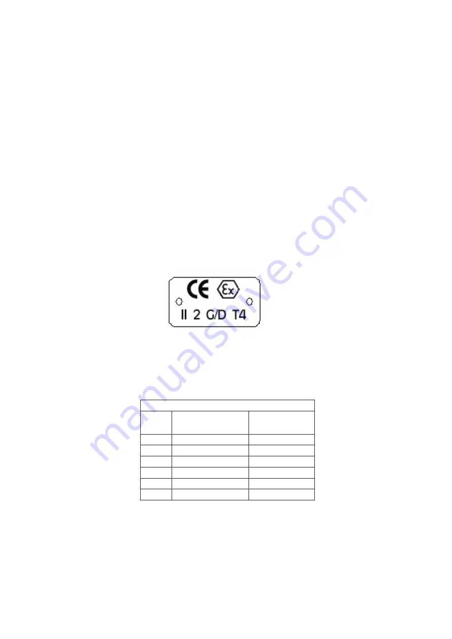
All pumping unit (pump, seal, coupling, motor and pump accessories) certified for use in an ATEX classified
environment, are identified by an ATEX tag secured to the pump or the baseplate on which it is mounted. A
typical tag would look like this:
The CE and the Ex designate the ATEX compliance. The code directly below these symbols reads as follows:
II
= Group 2
2 =
Category
2
G/D
= Gas and Dust present
T4
= Temperature class, can be T1 to T6 (see Table 1)
Table 1
Code
Max permissible
surface temperature
o
F (
o
C)
Max permissible
liquid temperature
o
F (
o
C)
T1
842 (450)
700 (372)
T2
572 (300)
530 (277)
T3
392 (200)
350 (177)
T4
275 (135)
235 (113)
T5
212 (100)
Option not available
T6
185 (85)
Option not available
The code classification marked on the equipment must be in accordance with the specified area where the
equipment will be installed. If it is not, do not operate the equipment and contact your ITT Goulds Pumps sales
representative before proceeding.
Содержание Goulds Pumps AF
Страница 1: ...Installation Operation and Maintenance Instructions Model AF 6 36 MXR Bearings ...
Страница 3: ...AF 6 36 IOM 6 THIS PAGE INTENTIONALLY LEFT BLANK ...
Страница 5: ...AF 6 36 IOM 8 THIS PAGE INTENTIONALLY LEFT BLANK ...
Страница 14: ...10 AF 6 36 IOM THIS PAGE INTENTIONALLY LEFT BLANK ...
Страница 32: ...28 AF 6 36 IOM ...
Страница 34: ...30 AF 6 36 IOM THIS PAGE INTENTIONALLY LEFT BLANK ...
Страница 48: ...44 AF 6 36 IOM THIS PAGE INTENTIONALLY LEFT BLANK ...
Страница 66: ...62 AF 6 36 IOM AF SECTIONAL shown with optional restrictor bushing adapter Fig 77 ...
Страница 68: ...64 AF 6 36 IOM AF OPTIONS Fig 78 351 370F 126 ...
Страница 69: ...AF 6 36 IOM 65 MXR BEARING CONFIGURATIONS 1MXR 3MXR 4MXR 6MXR Fig 79 540C 6 ...
Страница 72: ...68 AF 6 36 IOM THIS PAGE INTENTIONALLY LEFT BLANK ...


