background image

18-CHANNEL LED DRIVER EVALUATION BOARD GUIDE 

Integrated Silicon Solution, Inc. – ams.issi.com


Rev. B, 12/28/2018 

DESCRIPTION 

IS31FL3238 is an LED driver with 18 constant current 
channels. Each channel can be pulse width modulated 
(PWM) by 16 bits for smooth LED brightness control. 
In addition, each channel has an 8-bit output current 
control register which allows fine tuning the current for 
rich RGB color mixing, e.g., a pure white color LED 
application. The maximum output current of each 
channel is designed to be 76mA, which can be 
adjusted by one 8-bit global control register. 
Proprietary programmable algorithms are used in 
IS31FL3238 to minimize audible noise caused by the 
MLCC decoupling capacitor. All registers can be 
programmed via a high speed I2C (1MHz). 
 

FEATURES 

  2.7V to 5.5V VCC supply 

  Modulate LED brightness with 

256/1024/4096/65536 steps PWM method   

  Modulate LED DC current with 256 steps method 

  Global 256 steps analog global current control 

  PWM frequency selectable 

  Open short detect function 

 Spread 

spectrum 

 QFN-28 

(5mm×5mm) 

packages 


QUICK START 


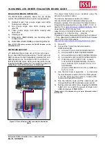
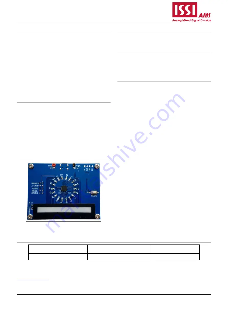
Figure 1: Photo of IS31FL3238

-

QWLS4 Evaluation Board 

RECOMMENDED EQUIPMENT 


5.0V, 2A power supply 


ABSOLUTE MAXIMUM RATINGS 


 5.5V power supply 

Caution: Do not exceed the conditions listed above, otherwise 
the board will be damaged. 


PROCEDURE 

The IS31FL3238 evaluation board is fully assembled 
and tested. Follow the steps listed below to verify 
board operation. 

Caution: Do not turn on the power supply until all connections 
are completed. 

1)  If using external DC power supply connect the 

ground terminal of the power supply to the 
evaluation board's GND pin and the positive 
terminal to the VCC pin. The evaluation board can 
also be powered via the Micro USB connector.   

2)  Short JP1 to disable external control. 

3)  Turn on the power supply/Plug in the Micro USB 

and pay attention to the supply current. If the 
current exceeds 1A, please check for circuit fault. 

4)  Enter the desired mode of display by toggling the 

MODE button (K1). 


ORDERING INFORMATION 

Part No. 

Temperature Range 

Package 

IS31FL3238-QFLS4-EB 

-40°C to +125°C (Industrial) 

QFN-28, Lead-free 

Table 1: Ordering Information 


For pricing, delivery, and ordering information, please contacts ISSI’s analog marketing team at 

[email protected]


or (408) 969-6600. 

Содержание IS31FL3238

Страница 1: ...QFN 28 5mm 5mm packages QUICK START Figure 1 Photo of IS31FL3238 QWLS4 Evaluation Board RECOMMENDED EQUIPMENT 5 0V 2A power supply ABSOLUTE MAXIMUM RATINGS 5 5V power supply Caution Do not exceed the conditions listed above otherwise the board will be damaged PROCEDURE The IS31FL3238 evaluation board is fully assembled and tested Follow the steps listed below to verify board operation Caution Do n...

Страница 2: ...n Atmel microcontroller with a bootloader allowing quick firmware updates First download the latest Arduino Integrated Development Environment IDE 1 6 12 or greater from www arduino cc en Main Software Also download the Wire h library from www arduino cc en reference wire and verify that pgmspace h is in the directory program Files x86 Arduino hardware tools avr avr include avr Then download the l...

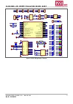
Страница 3: ...A15 JTDI 38 PB3 JTDO 39 PB4 JNTRST 40 PB5 41 PB6 I2C1_SCL TIM4_CH1 42 PB7 I2C1_SDA TIM4_CH2 43 BOOT0 44 PB8 TIM4_CH3 45 PB9 TIM4_CH4 46 VSS_3 47 VDD_3 48 U2 STM32F103C8T6 1 2 3 4 TP3 Header 4 GND SDA SCL SDB GND VDD CLK DIO VRGB VBlue VCC BIT1 BIT2 SDB VUSB 1 2 TP1 1 2 TP2 1 2 JP1 GND GND GND PA0 PA0 OUT01 OUT02 OUT03 OUT04 OUT05 OUT06 OUT07 OUT08 OUT09 OUT10 OUT11 OUT12 OUT13 OUT14 OUT15 OUT16 OU...

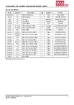
Страница 4: ...S240 Resistor R1 R3 RES 2k 1 10W 5 SMD 1 Yageo RC0603JR 072KL Resistor R2 R4 R6 R7 R8 RES 100k 1 10W 5 SMD 5 Yageo RC0603JR 07100KL Resistor R5 RES 3 3k 1 10W 5 SMD 1 Yageo RC0603JR 073K3L Resistor R9 RES 1k 1 10W 5 SMD 1 Yageo RC0603JR 071KL Resistor R10 R11 RES 22R 1 10W 5 SMD 1 Yageo RC0603JR 0722RL Resistor R12 RES 1 5k 1 10W 5 SMD 1 Yageo RC0603JR 071K5L Capacitor C1 C2 CAP 100nF 16V 20 SMD 2...

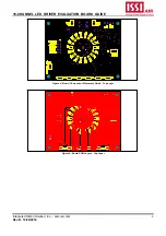
Страница 5: ... 12 28 2018 0 0 0 0 8 6 4 2 10 1 3 5 7 9 2 1 2 1 1 2 3 4 0 0 0 0 1 1 2 1 Figure 4 Board Component Placement Guide Top Layer 0 0 0 0 8 6 4 2 10 1 3 5 7 9 2 1 2 1 2 1 2 1 2 1 2 1 2 1 2 1 2 1 2 1 2 1 2 1 2 1 2 1 2 1 2 1 2 1 2 1 1 2 2 1 2 1 1 2 3 4 29 0 0 0 0 1 1 2 1 Figure 5 Board PCB Layout Top Layer ...

Страница 6: ... out of the application or use of any information products or services described herein Customers are advised to obtain the latest version of this device specification before relying on any published information and before placing orders for products Integrated Silicon Solution Inc does not recommend the use of any of its products in life support applications where the failure or malfunction of th...

Страница 7: ...DRIVER EVALUATION BOARD GUIDE Integrated Silicon Solution Inc ams issi com 7 Rev B 12 28 2018 REVISION HISTORY Revision Detail Information Data A Initial Release 2018 09 17 B Update schematic and PCB layout 2018 12 28 ...

Страница 8: ...HIGH SDB_HIGH delay 100 keep 0 5s Init_FL3238 void loop put your main code here to run repeatedly delay 50 Init_FL3238 IS31FL3238_mode1 breath mode void IS_IIC_WriteByte uint8_t Dev_Add uint8_t Reg_Add uint8_t Reg_Dat Wire beginTransmission Dev_Add 2 Wire write Reg_Add sends regaddress Wire write Reg_Dat sends regaddress Wire endTransmission stop transmitting void Init_FL3238 void uint8_t i 0 for ...

Страница 9: ...TION BOARD GUIDE Integrated Silicon Solution Inc ams issi com 9 Rev B 12 28 2018 IS_IIC_WriteByte Addr_GND i PWM_Gamma64 j write all PWM set 0x80 IS_IIC_WriteByte Addr_GND 0x49 0x00 update PWM congtrol registers delay 10 keep 0 5s ...

Отзывы: