background image


__________________________________________________________________________________ 

7 | 

P a g e - S e i t e


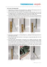
b.)


Process for braided cable: 

1.


Repeat steps 1 through 3 according to figure 1a.), adding the following operation for 
either termination under shrinking sleeve or with cable lug.


2.


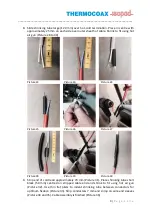
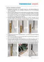
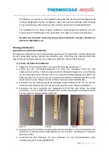
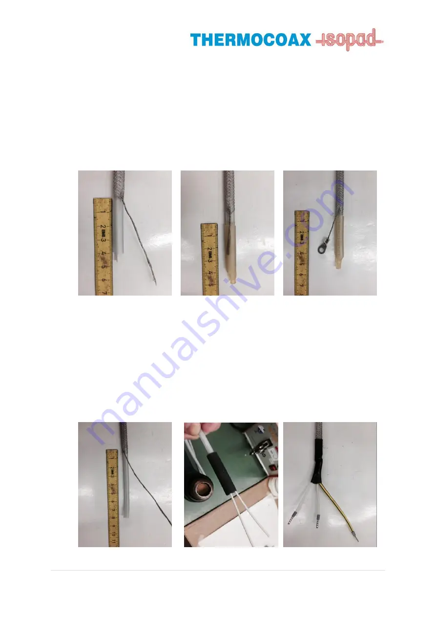
Remove braid using needle and twist remaining wires at approximately 45 mm at end 
of  cable  (Picture  13).  Cut  twisted  braid 10  mm  from  end  of  cable.  Slide translucent 
shrinking sleeved over end with braid beneath and shrink to fit (Picture 14).


3.


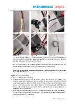
Optional Assembly with cable lug for earth termination. Do not cut twisted braid and 
slide  beneath  shrinking  sleeve.  Crimp  cable  lug  onto  drilled  braid  taking  the  wires 
double about 5 mm for better fit (Picture

 15). 


Picture 13 


Picture 14 


Picture 15 


4.


Repeat steps 4 through 5 according to figure 1a.), adding the following operation for 
termination with braid. 

5.


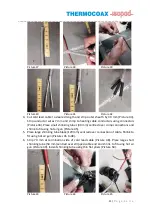
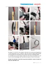
Remove braid using needle and twist remaining wires at approximately 80 mm at end 
of cable (Picture 16). 

6.


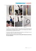
Use  green  yellow  shrinking  tube  (if  necessary  cut  to  length)  and  place  over  drilled 
braid. Use hot air gun to shrink to fit. Place large short shrinking tube black centred 
over stripped cable ends including green yellow tube. Use hot air gun to shrink to fit 
(Picture 17). Strip conductor wire insulation on insulated  ends 7 mm and use crimp 
tool to assemble wire end sleeves (Picture 18). If terminated right the green yellow 
part should be slightly longer than the conductors


Picture 16 


Picture 17 


Picture 18 


Содержание FG200 Series

Страница 1: ...1235 AM FG200 R15 0 ASSEMBLY MANUAL MONTAGE ANLEITUNG HEATING CABLE HEIZB NDER SERIES SERIE FG200 FG200B...

Страница 2: ...In addition THERMOCOAX ISOPAD GMBH reserves the right to make changes without notification to the Buyer to processing or materials that do not affect compliance with any applicable specification _____...

Страница 3: ...nmental information for industrial customers within the European Union To demand of the European Directive 2002 95 EC and of the national Product Safety Act equipment that is equipped with this symbol...

Страница 4: ...FG200 CONNECTION KIT TXI PN 1235 03681000 b Heating Cable Type FG200 unbraided or FG200B braided c Hot air gun d Ruler e Cutter knife and or standard knife f Scissors g Thin flat pliers h Crimping to...

Страница 5: ...To prevent from sticking the silicone outer sheath of the cable is covered in talc Clean areas to be assembled with a dry towel to remove talc residue before operation 2 Indicate the contact point at...

Страница 6: ...air gun to shrink to fit Use flat pliers to indent shrinking tube between conductor wires Picture 11 Strip conductor wire insulation on both ends 7 mm and use crimp tool to assemble wire end sleeves P...

Страница 7: ...cable lug onto drilled braid taking the wires double about 5 mm for better fit Picture 15 Picture 13 Picture 14 Picture 15 4 Repeat steps 4 through 5 according to figure 1a adding the following opera...

Страница 8: ...s for un braided cable 1 Follow steps 1 through 3 under Assembly Method 1a 2 Indicate Contact Point at end of heated section for electrical termination side Indicate next contact point and cut cable d...

Страница 9: ...28 to 30 Picture 22 Picture 23 Picture 24 Picture 25 Picture 26 Picture 27 Picture 28 Picture 29 Picture 30 9 Strip end of cold lead approximately 70 mm Picture 31 Place shrinking tube short black 50...

Страница 10: ...good contact with the object to be heated over the entire installation b Process for braided cable 1 See step 1 through 3 under 1b 2 Indicate Contact Point at end of heated section for electrical ter...

Страница 11: ...nectors Picture 44 Place small shrinking tubes 30 mm centred over crimp connections and shrink to fit using hot air gun Picture 45 5 Place large shrinking tube black 120 mm centred over connection of...

Страница 12: ...Please observe minimum cable spacing and bending radius for installation as well as maximum circuit length per type Refer to product data sheet for additional information For field termination with lo...

Страница 13: ...b der Europ ischen Union Die Europ ische Richtlinie 2002 95 EC und das deutsche Produktsicherheitsgesetz verlangen dass technische Ausr stung die direkt am oder mit dem Produkt und oder an der Verpack...

Страница 14: ...NNECTION KIT TXI PN 1235 03681000 b Heizkabel Typ FG200 ohne Geflecht oder FG200B mit Geflecht c Heissluftpistole d Lineal e Scharfes Messer f Schere g Schmale lange Flachzange h Crimp Werkzeug f r St...

Страница 15: ...tierungspunkten Das Kabel ist mit einer Talkumschicht versehen und sollte vor der Montage mit einem trockenen Tuch gereinigt werden 2 Finden Sie den Kontaktierungspunkt am Ende des Heizkabels Bild 1 M...

Страница 16: ...erten Kabelende Bild 10 Schrumpfen Sie den Schlauch passend mit einer Heissluftpistole Dr cken Sie den Schlauch zwischen den beiden Leitern mit Hilfe der d nnen Flachzange zusammen Bild 11 Manteln Sie...

Страница 17: ...ale Montage mit Kabelschuh zum Anschluss an Erdung Schneiden Sie die verdrillten Dr hte nicht ab Montieren Sie den Kabelschuh indem Sie die verdrillten Dr hte am Ende ca 5 mm doppelt legen f r besser...

Страница 18: ...ohne Geflecht 1 Folgen Sie den Arbeitsschritten 1 bis 3 gem Montage Methode 1a 2 Finden Sie den Kontaktierungspunkt am Ende der beheizten Zone f r den elektrischen Anschluss Finden Sie den n chsten Ko...

Страница 19: ...den Schlauch mittig ca 25 mm auf jeder Seite ber dem Aussenmantel der Kabel Schrumpfen Sie diesen passend mit der Heissluftpistole Bild 28 bis 30 Bild 22 Bild 23 Bild 24 Bild 25 Bild 26 Bild 27 Bild 2...

Страница 20: ...sind empfehlen wir den Einsatz unserer Kaltleitungen oder passenden Leitungen zu unserem Anschlussset Hinweis Das Heizkabel muss ber die gesamte Installation im guten Kontakt zur beheizten Oberfl che...

Страница 21: ...ab Bild 43 Manteln Sie die Innenleiter 7 mm ab und verbinden Sie die Leiter und die verdrillten Dr hte der beiden Kabel mit Stossverbindern Bild 44 Platzieren Sie die Schrumpfschl uche mittig ber den...

Страница 22: ...n Sie den Mindestverlegeabstand und den Biegeradius bei der Installation sowie die maximal zul ssige Heizkreisl nge je nach Ausf hrung Informationen hierzu finden Sie auf dem Produktdatenblatt F r Ins...

Страница 23: ...__________________________________________________________________________________ 23 P a g e S e i t e Notes Notizen __________________________________________________________________________________...

Страница 24: ...elektrischen Schutz kann das Heizkabel auch mit Metallgeflecht geliefert werden Heizkabelaufbau Technische Details Kabel Spezifikation 10 W m 20 W m 30 W m 40 W m Abmessung ohne Geflecht Abmessung mit...

Страница 25: ...eschreibung Kabel mit Geflecht AC 110 V FG200B 10W M 110V FG200B 20W M 110V FG200B 30W M 110V FG200B 40W M 110V Artikelnummer 1235 03680110 1235 03680120 1235 03680130 1235 03680140 Zubeh r Artikelbes...

Страница 26: ......
Страница 27: ...__________________________________________________________________________________ 23 P a g e S e i t e Notes Notizen __________________________________________________________________________________...

Страница 28: ...fo isopad solutions com Web www isopad solutions com www thermocoax com ____________________________________________________________________ ISOPAD is a trademark of THERMOCOAX ISOPAD GmbH or its affi...

Отзывы: