


Quick Installation Guide
4
Power Connecting
DC Power Connection
The switch can be powered from two power supply (input range 12V
– 58V). The DC power connector is a 4P terminal block; insert the positive and
negative wires into V+ and V- contact on the terminal block and tighten the wire-clamp screws to prevent the wires from being loosened.
After completing chassis installation, please apply power to the fused power distribution panel feeding the chassis.
Note The DC power should be connected to a well-fused power supply.
AC Power Connection
If you use AC power, connect the AC power cord to the AC supply socket on the rear panel, and plug the cord into the external power source. The
voltage must be 100 to 240 V (±10% tolerance).
Warning: Ensure that all power sources to the chassis (power distribution panel) are turned off
during the connection.
Ethernet Interface Connecting (RJ45 Ethernet)
IS-RG528 series provides two types of electrical (RJ45) and optical (mini-GBIC) interfaces.
Connecting the Ethernet interface via RJ45:
To connect to a PC, use a straight-through or a cross-over Ethernet cable,
To connect the switch to an Ethernet device, use UTP (Unshielded Twisted Pair) or STP (Shielded Twisted Pair) Ethernet cables.
Ethernet Interface Connecting (Fiber, SFP)
For a 1000 Mbps fiber port available, please use the mini-GBIC SFP. These accept plug in fiber transceivers that typically have an LC style connector.
For a 100 Mbps fiber port (port 25 & 26 only) available, please prepare the LC connectors or SC connectors (with the use of an optional SC-to-LC
adapter).
They are available with multimode, single mode, long-haul or special-application transceivers.
DANGER: Never attempt to view optical connectors that might be emitting laser energy.
Do not power up the laser product without connecting the laser to the optical fiber
and putting the cover in position, as laser outputs will emit infrared laser light at this
point.
Console Connection
The Console port is for local management by using a terminal emulator or a computer with terminal emulation software.
DB9 connector connect to computer COM port
Baud rate: 115200bps
8 data bits, 1 stop bit
None Priority
None flow control
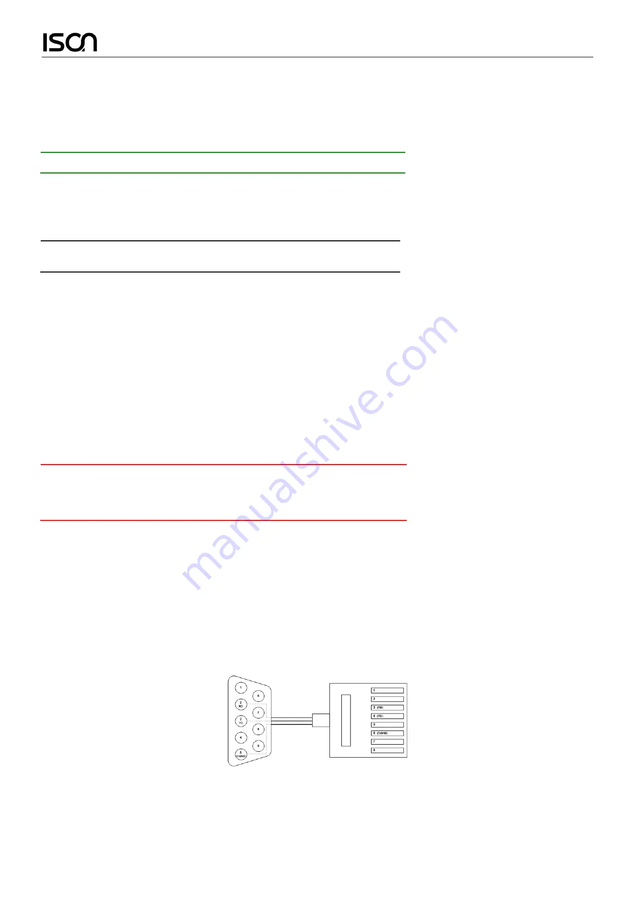
To connect the host PC to the console port, a RJ45 (male) connector-to-RS232 DB9 (female) connector cable is required. The RJ45 connector of the
cable is connected to the CID port of IS-RG528 series; the DB9 connector of the cable is connected to the PC COM port. The pin assignment of the
console cable is shown below:
Connect & Login to IS-RG528 series
1.
Connecting to IS-RG528 series Ethernet port (RJ45 Ethernet port).
2.
Factory default IP: 192.168.0.1
3.
Login with default account and password.
Username: admin


