background image

iSMA-B-MG-IP User Manual

www.ismacontrolli.com

DMP260en | 1st Issue rev. 6 | 05/2022

page 21 of 29

Figure 14. M-Bus tree topology

Separator

Figure 15. M-Bus extended star topology

6.4  M-Bus Settings

6.4.1  About M-Bus

The M-Bus (Meter Bus) was developed to fill the need for a system for networking and 

remote reading of utility meters, for example, to measure a consumption of gas or water 

in the house. This bus fulfils special requirements of remotely powered or battery driven 

systems,  including  consumer  utility  meters.  If  interrogated,  the  meters  deliver  the  data 

they have collected to a common master, for example, a DDC controller or a hand-held 

computer, connected at periodic intervals to read all utility meters of a building.

Topology and Cable

The  M-Bus  is  a  hierarchical  system,  with  communication  controlled  by  a  master  device 

(for example, the AAC20-M). The M-Bus consists of a master, a number of slaves (end-

Содержание iSMA-B-MG-IP

Страница 1: ...www ismacontrolli com DMP260en 1st Issue rev 6 05 2022 iSMA B MG IP User Manual ...

Страница 2: ...ngs 10 4 8 1 Restoring Default Settings 11 5 Modbus Gateway 12 5 1 Communication 13 5 1 1 RS485 Connection 13 5 2 Modbus Settings 14 5 2 1 Setting Modbus Address 14 5 2 2 Setting Baud Rate 14 5 2 3 Setting Protocol 15 5 3 Modbus Configuration Registers 15 5 3 1 Device Address 30002 15 5 3 2 Baud Rate and Protocol 30003 15 5 3 3 Counter of Received Messages 30004 16 5 3 4 Counter of Error Messages ...

Страница 3: ...on Bus 20 6 4 M Bus Settings 21 6 4 1 About M Bus 21 6 4 2 M Bus Addressing 22 6 5 M Bus Configuration Registers 22 6 5 1 Counter of Received Messages 30015 22 6 5 2 Counter of Sent Messages 30017 22 6 5 3 Counter of Alarms 30019 23 7 iSMA B MG IP WEB Configuration 24 7 1 Web Server Access 24 7 2 Device Page 24 7 3 M Bus Configuration 24 7 4 RS485 Configuration 25 7 5 IP Configuration 26 7 6 Devic...

Страница 4: ...sions or both at the same time using the same Ethernet connection The iSMA B MG IP allows to service up to 128 Modbus RTU ASCII devices with unique addresses connected to a COM1 port and up to 60 M Bus meters with unique addresses connected to an M Bus interface At the same time the iSMA B MG IP can manage up to 2 M Bus UDP IP clients 4 M Bus TCP IP clients 4 Modbus TCP IP clients which means it c...

Страница 5: ...page HW version RS485 biasing 1 2 26 Oct 2018 Corrections of typing errors in the text Added imperial unit of measure 1 3 15 Nov 2018 Added M Bus extended star and tree topology 1 4 11 Feb 2019 Added MBUS BAUD RATE 32 bits registers Added MBUS CONNECTION TIMEOUT 32 bits registers 1 5 8 Jun 2020 Company data update M Bus UDP IP protocol update Modbus function 0x17 read write multiple registers Modb...

Страница 6: ...henomena like surges and bursts to devices They also isolate products from inductive phenomena from other transformers and loads Power supply systems for the product should be protected by external devices limiting overvoltage and effects of lightning discharges Avoid powering the product and its controlled monitored devices especially high power and inductive loads from a single power source Powe...

Страница 7: ...rom 2400 to 115200 set by switch Address 0 to 99 set by switch M Bus Interface M Bus Up to 60 devices Baud rate From 300 to 38400 Ethernet 1 Fast Ethernet IP Interface Baud rate 10 100 Mb s USB USB Mini USB 2 0 Ingress protection IP IP40 Temperature Storage 40 C to 85 C 40 F to 185 F Operating 10 C to 50 C 14 F to 122 F Humidity Relative 5 to 95 Connectors Type Removable Maximum cable size 2 5 mm2...

Страница 8: ...osures along with other devices which generate electromagnetic radiation for example relays contactors transformers motor invertors etc Such electromagnetic radiation can induce electrical noise into both power and signal lines as well as direct radiation into the controller causing negative effects on the system For this reason an appropriate grounding shielding and other protective steps should ...

Страница 9: ...MA B MG IP it is 5910 0x3B16 High byte contains the device firmware version multiplied by 10 For example In the 30001 register the number is 1511410 0x3B0A16 It means that it is a iSMA B MG IP device 0x3B with firmware in version 1 0 0x0A16 1010 4 5 Uptime 30012 This 32 bits register contains information about uptime in seconds The value is reset after a power cycle 4 6 Device Actions 40001 Settin...

Страница 10: ...RS485 port If the device receives sends a lot of messages the LED can be lit continuously The communication ETH1 LED is on orange for 20 ms after sending each message by the Ethernet If the device receives sends a lot of messages the LED can be lit continuously The ALM LED is ON green if an overload is detected on the M Bus bus current on the M Bus bus exceeds 130 mA 4 8 Default Settings Out of th...

Страница 11: ... RATE 2400 MBUS TCP PORT 6021 MBUS UDP PORT 10002 Table 4 Default values 4 8 1 Restoring Default Settings To restore the default configuration of all registers follow the steps below Turn off the power supply Set section 6 of the S3 switch to on Turn on the power supply power LED is blinking Switch section 6 of the S3 switch to off to restore the default settings To cancel the reset turn off the p...

Страница 12: ...t 60 s if there is no request from the Modbus TCP client during this time the device will close the connection To read internal registers of the device it needs to generate the correct Modbus TCP frame with address according to the setting of a DIP switch If the address is different the frame will be sent to the COM1 port If the device receives an incorrect Modbus TCP frame it sends back a frame w...

Страница 13: ...e slave device answers the correct frame it is converted to Modbus TCP and sent to the master device The meter gateway sends an error code 0x0B in case the valid frame is not received Upon receipt of this error code some systems do not repeat the query according to the settings No retry may cause the point to immediately go to down mode That is why the meter gateway has the ability to block the se...

Страница 14: ...ss S2 10 S1 where S1 and S2 are values of switches For example Figure 8 Setting Modbus address with rotary switches Switches set as in figure above will set the device address to 11 5 2 2 Setting Baud Rate Transmission baud rate is determined by the S3 DIP switch sections 1 2 and 3 in accordance with the following table 1 2 3 Baud Rate Off 0 Off 0 Off 0 Defined by the user in the register Off 0 Of...

Страница 15: ...his address is set by using switches S1 and S2 see Modbus Settings section 5 3 2 Baud Rate and Protocol 30003 The register contains information about the baud rate of COM1 port and the type of protocol in accordance with the table below This register reflects the state of the S3 DIP switch Baud rate Protocol Bit 0 Bit 1 Bit 2 Baud rate Bit 3 Bit 4 Protocol 0 0 0 User defined 0 0 Modbus RTU 0 0 1 7...

Страница 16: ...sages 30008 The 32 bit register with the number of Modbus messages sent by the device from last powering up The value is reset after a power cycle or after changing transmission parameters speed stop bits parity etc 5 3 6 Hardware_Version 30130 This 16 bits register contains the module hardware version multiplied by 10 5 3 7 MAC_Address 30131 This 32 bits register contains the module MAC address i...

Страница 17: ...e in MG IP devices with a hardware version 2 0 or higher The biasing resistors are useful in case the iSMA modules are connected with a third part devices with the same RS485 bus and communication errors appears on the network Figure 9 Modbus frame 5 3 11 Data Bits 40138 Number of data bits transmitted in a single byte is determined according to the following table Value No of Data Bits 7 7 8 defa...

Страница 18: ...nes in a byte is even 3 Always 1 4 Always 0 Table 11 Parity bit 5 3 13 Response Delay Time 40140 The value of this 16 bits register determines the number of milliseconds to wait before the device answers the question This time is used to extend the interval between question and answer The default value of 0 means no delay the answer is sent once during the 3 5 character required by the Modbus RTU ...

Страница 19: ...s devices using the bus In order to ensure proper operation of the M Bus gateway please make sure that the baud rate of the M Bus interface of all the devices connected to the bus gateway and an addition devices are the same Operation of the gateway is based on sending the M Bus TCP IP query by the M Bus Data frame from query is converted to M Bus and sent to the bus Then the iSMA B MG IP device w...

Страница 20: ...n 1st Issue rev 6 05 2022 page 20 of 29 Figure 11 UDP packets delivery Both TCP and UDP protocols share the M Bus interface Figure 12 M Bus shared interface 6 3 M Bus Communication 6 3 1 Connecting Communication Bus Figure 13 M Bus start topology Separator ...

Страница 21: ...a consumption of gas or water in the house This bus fulfils special requirements of remotely powered or battery driven systems including consumer utility meters If interrogated the meters deliver the data they have collected to a common master for example a DDC controller or a hand held computer connected at periodic intervals to read all utility meters of a building Topology and Cable The M Bus i...

Страница 22: ...t of a maximum cable capacitance of 180 nF 6 4 2 M Bus Addressing M Bus devices are using two types of addressing Primary this address is assigned by a user in a commissioning process all new M Bus devices have this address set by default to 0 This type of address has a limited range from 0 to 250 Secondary this address has a wider range than primary and by default contains a device serial number ...

Страница 23: ...05 2022 page 23 of 29 6 5 3 Counter of Alarms 30019 The 16 bit register with the number of M Bus alarms from last powering up An alarm is detected if current bus exceeds acceptable level 130 mA The value is reset after a power cycle or after changing transmission parameters ...

Страница 24: ...t IP address is 192 168 1 123 Please use the following credentials Username platform Password 1000 default 7 2 Device Page This page contains information and technical specification of the device The Basic Information section includes information about a device type firmware version and uptime In the Device Specification section there are information about power supply inputs outputs parameters in...

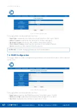
Страница 25: ... frames Transmitted Frames read only the number of transmitted frames Alarms read only the number of M Bus alarms 7 4 RS485 Configuration This page allows to enter configuration parameters and show information of the device s COM1 port Figure 19 RS485 configuration page This page allows to set parameters such as Baud rate read only the RS485 baud rate from 2400 up to 115200 Modbus Config read only...

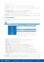
Страница 26: ...ller s Ethernet interface IP address Mask read write the network mask Gateway read write the network default gateway Http Port read write the http port Mac Address read only the Ethernet interface MAC address M Bus TCP Port read write the M Bus TCP port number default 6021 M Bus UDP Port read write the M Bus UDP port umber default 10002 Protocol Type read only the DIP switch protocol selection Mod...

Страница 27: ...in the Current Device Password field Enter the new device password in the New Device Password field Enter the new device password again in the Confirm New Device Password field To confirm the password change please click the Submit button Log out and log in again using the new password 7 7 Contact This page displays information about the Manufacture s website and e mail to technical support Figure...

Страница 28: ...rameters 30008 7 0x07 MODBUS TRANSMITTED FRAMES COUNTER 32 bits Read only Default state is 0 Reset at the device start and change of transmission parameters 30012 11 0x0B UP TIME Up device time in sec 30015 14 0x0E M BUS RECEIVED FRAMES COUNTER Read only Default state is 0 Reset at the device start and change of transmission parameters 30017 16 0x10 M BUS TRANSMITTED FRAMES COUNTER Read only Defau...

Страница 29: ... calculated using the formula The value is considered only when sections 1 2 and 3 of S3 switch is in the OFF position The default value is 7680 76800 bps 40137 136 0x88 STOP BITS Read write memory Supported values are 1 and 2 The default value 1 40138 137 0x89 DATA BITS Read write memory Supported values are 7 and 8 The default value 8 40139 138 0x8A PARITY BIT Read write memory Parity Bit 40139 ...

Отзывы: