background image

APPENDIX

Содержание BC-300

Страница 1: ...SERVICE MANUAL Manual No 0141A ISHIDA CO LTD Retail Scale BC 3000 48775 ...

Страница 2: ...ay Unit Replacement 3 7 3 5 Load Cell Replacement 3 8 4 ELECTRONIC CONFIGURATIONS 4 1 4 1 Connector Configuration 4 1 4 2 Power Unit 4 2 4 3 Main Board P 864 4 3 4 4 A D Board P 830 4 5 4 5 Keyboard 4 5 4 6 Display Unit P 856 4 6 4 7 DC DC Converter 4 7 4 8 Connector Bracket 4 7 4 9 Label Sensor 4 8 5 THERMAL HEAD 5 1 5 1 Overview 5 1 5 2 Specifications 5 1 5 3 Thermal Head Adjustment 5 2 5 4 Ther...

Страница 3: ...n Select b11 S4 7 7 Total Mode Select b12 S4 8 8 Password b13 S4 8 9 Default PLU b14 S4 8 S5 TEST MODE S5 1 S5 1 Menu Schematic S5 1 S5 2 Test Mode Procedures S5 2 1 Hardware Test C01 Calibration S5 2 2 RAM Clear C02 S5 6 3 Thermal Head C03 S5 7 4 Sensor Check C04 S5 8 5 Memory Check C05 S5 9 6 ROM Switch Number Select C06 S5 9 7 Label Format C07 S5 10 8 Sales Mode C08 S5 11 10 Preset Function Key...

Страница 4: ...HARDWARE SECTION ...

Страница 5: ...BC 3000 Service Manual Rev 1 1 1 Chapter 1 Introduction 1 INTRODUCTION 1 1 MAIN COMPONENTS ...

Страница 6: ...printing density can be set by key entry Settable sales mode For supermarket specifications there are operator and non operator selections Differences from the AC 2000 Data transmission to the IF 21FD is via I2 NET 9P instead of RS 232C used by the AC 2000 An inspection mode has been added Verification can be made during totaling Mode Key Function Enter the pass code 4 digits then press MODE to ch...

Страница 7: ...r other liquids Scale will not be exposed to direct sunlight for long periods Scale will not be exposed to wind or strong vibration Installation site should be sufficiently spacious Dedicated grounded circuit is available 2 3 ASSEMBLY Assemble the display components as follows 1 Thread the display connector cable through the display pole 2 Attach display pole to the plastic display housing with 2 ...

Страница 8: ...ngth setting Chapter S4 Setting Mode 1 Label Format Sales mode setting Chapter S5 Test Mode 8 Sales Mode 3 Register date and time Referring to the programming manual enter the date and time 4 Register PLU Referring to the programming manual enter PLU data registration in Registration mode 5 Perform print test Load a roll of labels or receipts and confirm that printing is correct Refer to Chapter S...

Страница 9: ...hapter explains the procedures for disassembling and replacing the main components Please be careful not to drop or strongly impact fragile parts such as the display unit and circuit boards Also before disassembly be sure to turn off the power switch and unplug the power cord 3 1 DISASSEMBLY VIEW AND PART NAMES ...

Страница 10: ... H 1 1 S A e s u F 2 1 w a s e e S h c t i w S 3 1 d r o c r e w o P 3 C s s e n r a H 4 1 C D C D y l p p u S r e w o P 5 1 I 3 C s s e n r a H 2 T E N 6 1 1 y a l p s i D 2 C s s e n r a H 7 1 1 C D C D 2 S s s e n r a H 8 1 L x 4 2 1 L X t l e B g n i m i T 9 1 e b u t s s a l G e s u F 0 2 g n i p p e t S S A r o t o M 1 2 r e w o P 3 S s s e n r a H Note Only the main parts are listed here Fo...

Страница 11: ...the scale if necessary 2 Unplug the power plug from its outlet 3 Lift off the weigh platter keeping it horizontal When replacing the weigh platter align the platter pins with the rubber inserts on the platter base 2 Remove the platter base Remove the four attachment screws then lift off the platter base After replacing the platter base perform four corner adjustment Refer to Section 5 5 Note Note ...

Страница 12: ...he display pole CAUTION In order to avoid damage to fragile components be careful not to drop or strongly impact them 4 Remove the operation keyboard panel 1 Cut the base seal wire 2 Remove base seal wire screw B 3 Remove both screws C The base seal wire is only used for countries requiring a base seal For other specifications remove only screws B C CAUTION After the base seal wire is cut it is ne...

Страница 13: ...irection of the arrow 2 Cut the seal wire and remove the seal wire screws 3 Remove the four screws which secure the upper case then carefully lift the cover off the main body CAUTION After the base seal wire has been cut it is necessary to have the scale re inspected and the seal replaced Never cut the base seal unless required ...

Страница 14: ...e attachment screw from the main board 2 Slide the main board toward you and remove connectors 3 8 3 Remove the keyboard 1 Remove connectors 9 and 10 located on the main board beside the keyboard 2 Peel off the keyboard starting from the corner CAUTION If the keyboard is removed even once it becomes unusable Never remove unless necessary 4 Remove the A D board Remove the A D board referring to the...

Страница 15: ...sassembly Replacement 3 4 DISPLAY UNIT REPLACEMENT Replace display unit 1 Carefully remove the cover 2 Remove the four screws which secure the display unit CAUTION To avoid damage to the cover open it slowly and carefully Avoid touching the display unit ...

Страница 16: ...load cell unit 2 Remove the load cell unit 3 Remove the A D board 1 Remove the screw which secures the A D board 2 Slide theA D board from its plastic bracket and disconnect Connector A 3 Remove the load cell output cable soldered in five places CAUTION The load cell output cable has five soldered points When replacing be sure that the wires are in the correct order After replacing the load cell u...

Страница 17: ...BC 3000 Service Manual Rev 1 4 1 Chapter 4 Electronic Configurations 4 ELECTRONIC CONFIGURATIONS 4 1 CONNECTOR CONFIGURATION ...

Страница 18: ...tronic Configurations 4 2 POWER UNIT The power unit performs efficient voltage conversion stabilizes low voltage and supplies power to the various units External View Block Diagram 1 N C P 0 0 1 S L S 1 V 5 1 1 o t 0 0 1 C A 3 V 5 1 1 o t 0 0 1 C A ...

Страница 19: ...s 4 3 MAIN BOARD P 864 This board is equipped with a 16 bit microprocessor and is used to process scale data The board is multi layered and its high precision construction is designed to reduce electrical impedance electrical noise and static electricity External View ...

Страница 20: ...g output I2 NET output Label sensor input Battery Switch A lithium memory backup battery is included in these units Afterinstallation makesurethebatteryswitch is set to ON This scale uses a rechargeable lithium battery Normal charge is 3 6V Battery switch is set to ON at time of shipment from factory CAUTION There is danger of explosion if this battery is incorrectly replaced Replace only with the...

Страница 21: ...ARD P 830 The A D board converts analog weight data from the load cell into digital data and performs automatic span control and zero compensation External View 4 5 KEYBOARD This is a panel type keyboard A flexible cable connects it to the main keyboard CN9 and CN10 External View ...

Страница 22: ...AY UNIT P 856 The BC 3000 is equipped with a 7 segment display module Weight price and unit price data are displayed External View CAUTION The display modules are made of glass so care should be taken not to touch or impact the units Do not remove the connectors with the power ON ...

Страница 23: ...pter 4 Electronic Configurations 4 7 DC DC CONVERTER The DC DC converter transfers the voltage supplied to the display board External View 4 8 CONNECTOR BRACKET Includes the power switch power cord fuse and I2 NET connectors External View ...

Страница 24: ...ronic Configurations 4 9 LABEL SENSOR The label sensor utilizes a photo interrupter to detect the gap between labels and functions to ensure that labels are printed correctly one at a time External View See Section 5 5 for adjustment procedures Note ...

Страница 25: ... a m r e h t y t i s n e d e l b u o D I 4 2 1 3 H L t n u o c t o d l l a r e v O s t o d 8 4 4 h c t i p t o D H m m 5 1 0 x W 5 3 1 0 e c n a t s i s e r d a e H 2 7 6 o t 8 2 5 R Ω r e w o p d e r i u q e R t o d W 8 8 0 e g a t l o v d e i l p p A V 4 2 h t d i w t n i r p m u m i x a M m m 5 0 6 n o i t u l o s e R m m s t o d 4 7 h c n i s t o d 8 8 1 d e e p s t n i r P c e s m m 0 7 c e s...

Страница 26: ...int surface are aligned Print out another test label and note the print density If not satisfactory adjust the position of the thermal head then print another label Repeat until print density is correct After adjustment retighten the two attachment screws Thermal head is usually mounted flush and parallel with the front edge of the mounting plate CAUTION Avoid touching the surface of the head If t...

Страница 27: ...ects Never use thinner to clean the head as it may damage other parts of the scale 5 5 OTHER ADJUSTMENTS Four limit bolts in the platter base function to prevent damage to the load cell from weight overload Four corner adjustment is performed when the load cell is replaced or when external impact to the scale necessitates it 1 Four corner adjustment Place a weight equal to scale capacity 15kg 30lb...

Страница 28: ... The label and gap identification default setting value is 100 When using receipt paper for report printing this adjustment is not necessary MAIN BOARD LABEL SENSITIVITY ADJUSTMENT VOLUME VR1 The main board P 864 label sensor adjustment volume VR1 generally does not require adjustment it is set before factory shipment Label sensor adjustment is ordinarily through the adjustment method steps 1 and ...

Страница 29: ...ssages 6 1 PERIODIC PARTS REPLACEMENT MTBF The following parts need to be periodically replaced MTBF Mean Time Between Failures 1 Thermal head Replacement period When label advance distance reaches 30 km 2 Display module Display board Normal life expectancy Under normal usage conditions 30 000 hours 3 Print roller Replacement period When label advance distance reaches 300 km ...

Страница 30: ... v o m e R l l e c d a o l e c a l p e r t s u j d A d r a o b n i a m e c a l p e r k c e h C o d s t n e m g e s n i a t r e C e r a r o t h g i l t o n t i l y l s u o u n i t n o c g n i n n u r t o n m a r g o r P e v i t c e f e d d r a o b n i a M e v i t c e f e d d r a o b y a l p s i D s r o t c e n n o c k c e h C d r a o b n i a m e c a l p e r k c e h C d r a o b y a l p s i d e c a l...

Страница 31: ...e R M O R 2 E 2 4 r r E p u t r a t s t o n s e o d m a r g o r p n i a m n i n o i t c n u f l a M e r u l i a f d r a o b U P C e l b i s s o p k c e h C s p i h c e r a w m r i f k c e h C 3 4 r r E d e t p u r r o c n e e b s a h M O R 2 E n i y r o m e M r a e l c M O R 2 E h t i w e z i l a i t i n i e R 0 5 r r E g n i n o i t c n u f l a m r o d e t c e n n o c s i d s i d r a o b D A g n ...

Страница 32: ...6 4 BC 3000 Service Manual Rev 1 Chapter 6 Troubleshooting ...

Страница 33: ...SOFTWARE SECTION ...

Страница 34: ...BC 3000 Service Manual Rev 1 S1 1 Chapter S1 Outline of Software S1 OUTLINE OF SOFTWARE S1 1 MEMORY MAP ...

Страница 35: ...h d n a D 9 0 2 0 B e r a w m r i F g n i h g i e w e g n a R e l g n i S r e h g i h d n a 2 1 3 0 B e r a w m r i F g n i h g i e w e g n a R l a u D t a m r o F l e b a L t a m r o F l e b a L 1 o N m m 4 4 x 0 6 1 o N m m 4 4 x 0 6 2 o N m m 7 4 x 4 6 2 o N m m 7 4 x 4 6 3 o N H S m m 5 8 x 4 6 3 o N H S m m 5 8 x 4 6 4 o N C P U n o N m m 7 3 x 4 6 4 o N H S m m 9 5 x 4 6 Product name referen...

Страница 36: ...n describes the procedures for selecting the root and submenus Root Menu Selection Procedure Enter the number of the Root menu to be displayed then press Press on the setting mode display to switch the root menus in sequence Sub Menu Selection Procedure Press ENTER on the root menu display Enter the number of the submenu to be displayed then press Press to switch the submenus in sequence Press END...

Страница 37: ...e Use By Department Group Item Code POP Extra Message Barcode Type Barcode Prefix 10 Digit Code Open Price Forced Tare Setting Mode Sub Menus 01 02 03 04 UPC Barcode Flag 10 Digit Flag Bar Code Type UPC Type 01 02 03 04 Department Code Group Code UPC 8 Reference Data UPC 13 Reference Data 1 Label Format b01 Bar Code 2 b02 b08 b04 b03 b01 b02 3 Code b03 b04 4 Initial Data Set 8 PLU File b08 01 04 0...

Страница 38: ... 14 Default PLU b14 b14 01 03 Daily Total Monthy Total 01 02 03 Registration Mode Total Mode Subtraction Mode 01 Default PLU Number 01 02 04 06 07 08 09 10 11 12 17 19 21 22 PLU File Commodity Name Extra Message Date Time Store Name Address Preset Key PLU List Departmennt Group Operator Machine Number On Line Setup Nutrition Price Change ...

Страница 39: ... e t n i r p e l t i T 1 s e l t i t t n i r p l l i w e l a c s f i t c e l e S 5 0 1 0 b e m a n e r o t S s s e r d d A d e t n i r p t o N 0 d e t n i r P 1 s s e r d d a d n a e m a n e r o t s t n i r p l l i w e l a c s f i t c e l e S 6 0 1 0 b y t i d o m m o C e n i L s p e t s 5 0 0 5 1 o t 5 0 0 1 e n i l 1 0 3 x 5 1 s r e t c a r a h c e e r h t e z i S 5 0 e n i l 1 4 1 x 7 s r e t c...

Страница 40: ... N 1 3 t l u a f e D 2 0 3 0 b p u o r G s t i g i d 2 y r t n e c i r e m u N 2 4 t l u a f e D 3 0 3 0 b e c n e r e f e R 8 C P U s t i g i d 2 y r t n e c i r e m u N 2 4 t l u a f e D 4 0 3 0 b e c n e r e f e R 3 1 C P U s t i g i d 2 y r t n e c i r e m u N 5 4 t l u a f e D Note o N u n e M n o i t p i r c s e D s r e t e m a r a P e t o N 1 0 2 0 b g a l F e d o c r a B C P U s t i g i d ...

Страница 41: ...d n i 1 y a d e m a s 3 0 4 0 b e m i T k c a P g n i s u y b m e t i t c e l e S 0 r e t n E t i b i h o r P 1 0 r e t n E l a n r e t n I 2 e m i t g n i t a c i d n i s t i g i d 4 r e t n E d e t a n g i s e D 3 0 0 4 1 r e t n e M P 2 r o f 0 0 8 r e t n e M A 8 r o f e l p m a x E d e t a n g i s e D M A 1 1 0 e m i t M P 3 2 o t 2 1 4 0 4 0 b e m i T e r i p x E g n i s u y b m e t i t c e ...

Страница 42: ...L A S 3 0 8 0 b N W O D K R A M 4 0 8 0 b E C I R P T I N U 5 0 8 0 b E C I R P X I F 6 0 8 0 b T H G I E W X I F 7 0 8 0 b E D O C I G E R 8 0 8 0 b Y T Q 9 0 8 0 b E C I R P T S O C 0 1 8 0 b E R A T 1 1 8 0 b T N I R P E T A D 2 1 8 0 b E F I L F L E H S 3 1 8 0 b Y B E S U 4 1 8 0 b T N E M T R A P E D 5 1 8 0 b P U O R G 6 1 8 0 b E D O C M E T I 7 1 8 0 b P O P 8 1 8 0 b E G A S S E M A R T ...

Страница 43: ...rect All Item settings 0 Prohibit 1 Permit Note o N u n e M n o i t p i r c s e D g n i t t e S 1 0 1 1 b e l i F U L P 2 0 1 1 b e m a N y t i d o m m o C 4 0 1 1 b e g a s s e M a r t x E 6 0 1 1 b e m i T e t a D 7 0 1 1 b e m a N e r o t S 8 0 1 1 b y e K t e s e r P 9 0 1 1 b t s i L 0 1 1 1 b t n e m t r a p e D 1 1 1 1 b p u o r G 2 1 1 1 b s r o t a r e p O 7 1 1 1 b o N e n i h c a M 9 1 ...

Страница 44: ... then press ENTER 1 The only value which cannot be entered is 6000 2 The setup menu password cannot be changed from 6000 Default PLU b14 Used to set the open PLU value Enter the numbers 6 digits then press ENTER To disable this feature enter 0 o N u n e M n o i t p i r c s e d g n i t t e S 1 0 2 1 b L A T O T Y L I A D 3 0 2 1 b L A T O T Y L H T N O M o N u n e M u n e M g n i t t e S t l u a f ...

Страница 45: ...C99 01 Mode C08 C99 02 Transfer File 03 Initialize Disk 01 02 03 04 05 A D Check Key Check Display Check I2 Net Check Program No 01 02 03 All RAM Clear E2 RAM Clear Test Set 01 02 03 I2 Net RAM CHeck Loop Back Test I2 Net Program No C01 04 C01 C03 C02 C10 C99 02 01 02 03 04 Thermal Head Print Usage in KM Print Density Label Sensor Adjust 00 02 03 05 06 07 08 09 10 12 Asterisk Key displays date tim...

Страница 46: ...nual Rev 1 Chapter S5 Test Mode AREA NO A D CONVERSION INITIAL VALUE S5 2 TEST MODE PROCEDURES 1 Hardware Test C01 1 A D Check C01 01 This item is used to calibrate the scale 4257 4257 10 A D CONVERSION VALUE SPAN ADJUSTMENT ...

Страница 47: ...nversion value is displayed in the weight column Check that the value is 30000 2 If it is perform data registration as described below If not 30000 2 press TARE remove the span weight and performA D Initial Value Setting again Data Registration This operation writes data into E2 ROM Remove the span weight then remove the weigh platter Press the switch as shown in the diagram at right Calibration d...

Страница 48: ...check display function Press ENTER to start the display check Press END to exit display check 1 2 3 4 5 6 7 8 9 0 1 1 1 2 1 3 1 4 1 5 1 6 1 7 1 8 1 9 1 0 2 1 2 2 2 3 2 4 2 5 2 6 2 7 2 8 2 0 3 1 3 2 3 3 3 4 3 5 3 6 3 7 3 8 3 9 3 0 4 1 4 2 4 3 4 4 4 5 4 6 4 7 4 8 4 9 4 0 5 1 5 2 5 3 5 4 5 5 5 6 5 7 5 8 5 9 5 0 6 1 6 2 6 3 6 4 6 5 6 6 6 7 6 8 6 9 6 0 7 1 7 2 7 3 7 4 7 5 7 6 7 7 7 8 7 9 7 0 8 1 8 2 8 ...

Страница 49: ...ed Loop Back Test C01 04 02 Press PRINT Confirm that PASS is displayed I2 NET Program No C01 04 03 The I2 NET Program No version will be displayed 5 Program No C01 05 This item is used to display the ROM version number of the main board Press to switch between the main and font ROM versions Step C01 05 00 Main program Step C01 05 01 Font program C01 04 01 PASS C01 04 02 PASS C01 04 03 id 4 C01 05 ...

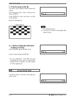
Страница 50: ...onfiguration changes programmed in the Setup Menu and Test Menu Press ZERO twice When E2 ROM data has been cleared PASS is displayed This step MUST be performed when upgrading EPROM firmware chips 3 Test Set C02 03 This item performs the same function as steps C02 01 and C02 02 above with the additional feature of creating the following test data PLUs 1 through 10 Store Name Address 1 Press ZERO t...

Страница 51: ... by pressing e u l a V e c n a t s i s e R e u l a V y r t n E 5 4 5 8 2 5 7 3 5 3 6 5 6 4 5 5 5 5 1 8 5 4 6 5 3 7 5 0 0 6 2 8 5 1 9 5 8 1 6 1 0 6 9 0 6 6 3 6 9 1 6 7 2 6 4 5 6 7 3 6 5 4 6 2 7 6 5 5 6 3 6 6 2 Print Usage in KM C03 02 This item is used to display in kilometers the amount of thermal head usage To clear usage data enter 0 then press ENTER PLEASE NOTE When replacing the thermal head b...

Страница 52: ...NT SAMPLE 4 Label and Gap Identification Setting C03 04 Set the label and gap identification value Input the value and press ENTER For an explanation of the label and gap identification set value refer to Label Sensor Adjustment P 5 4 Section 5 5 under Chapter 5 Other Adjustments 4 Sensor Check C04 This item is used to confirm the current label gap sensor value C03 03 5 C03 04 100 C04 00 255 1 The...

Страница 53: ...0 0 6 9 0 0 d u a b 0 0 8 4 2 0 d u a b 0 0 4 2 1 0 d u a b 0 0 2 9 1 4 0 d u a b 0 0 6 9 3 0 8 2 r e t f a t n e m e g d e l w o n k c a C P r o f e m i t t i a W e l a c s m o r f n o i s s i m s n a r t x e h F F o t 0 c e s m 5 5 2 o t 0 0 0 t l u a f e d A 2 n o i t a r e p o y e k T E S E R t l u a f e d e l b a n E 0 0 e l b a s i D 1 0 D 2 e t i l l e t a S r e t s a M C B o t C B e n i L ...

Страница 54: ...sing 0 X axis 1 Y axis 3 Select Print Field using or 4 Enter the new coordinate value then press ENTER 5 Press PRINT to print a test label 6 Press END to return to the main Test Menu Refer to Appendix A6 for worksheets of all default label formats C07 01 0 01 0324 NOTES To switch X and Y axis press Reposition graduation is 1 0 1mm LABEL Base Points X 0 Y 0 Y Axis X Axis COORDINATE PRINT FIELD 0 X ...

Страница 55: ...ODE 8 Sales Mode C08 1 Sales Mode C08 01 This item is used to set the sales mode most suitable for the user s application Enter the number corresponding to the desired mode then press ENTER C08 01 1 1 o N y r t n E e d o M s e l a S 1 r o t a r e p O M S o N 2 r o t a r e p O M S ...

Страница 56: ...U M o N y r t n E e m a N n o i t c n u F n o i t p i r c s e D 0 E M I T E T A D s d n o c e s 3 r o f e m i T e t a D s y a l p s i D 1 2 E G A S S E M e g a s s e m d a p u l l a C 3 E R O T S e m a n e r o t s p u l l a C 4 5 P O P P O P p u l l a C 6 E C I R P X I F e c i r p d e x i f t e S 7 E V A S U L P e v a S 8 T N U O C S I D e c i r P l a t o T w e N t n u o c s i d t e S 9 n o i t c ...

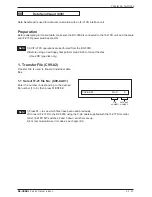
Страница 57: ...a new floppy disk perform step 99 03 to format the disk Use 2DD type disk only 1 Transfer File C99 02 Transfer File is used to transmit individual data files 1 1 Select IF 21 file No C99 02 01 Enter the number corresponding to the desired file number 1 to 8 then press ENTER 1 Press to see which files have been used previously 2 Connect IF 21FD to the BC 3000 using the 9 pin cable supplied with the...

Страница 58: ...ote C99 02 03 No 0 0 1 Master File contains all data programmed in Registration Mode E2 ROM File contains all configuration setting changes made in Setup and Test Modes 2 Master File contains file numbers 4 9 and 12 21 3 E2 ROM File contains file numbers 10 Label Format and 11 Setup File IMPORTANT When upgrading firmware or transferring files from one model to another DO NOT load 11 SETUP FILE Thi...

Страница 59: ...file OK is displayed after the file has been deleted Select the file as shown in step 1 1 above File is compatible with other 3000 Series scales C99 02 05 No 0 0 o N y r t n E n o i t c n u F o N y r t n E n o i t c n u F 1 s e l i F l l A 2 1 2 e l i F r e t s a M 3 1 3 E2 e l i F M O R 4 1 e l i F e l t i T 4 r e t s a M m e t I 5 1 t n e m t r a p e D 5 r e t s a M e r o t S 6 1 p u o r G 6 7 1...

Страница 60: ...y disk press CHAR DELETE To terminate deletion in progress press any other key than CHAR DELETE 2 2 OK to delete C99 03 02 To execute disk initialization press CHAR DELETE To terminate deletion in progress press any other key than CHAR DELETE 2 3 OK to delete C99 03 03 Disk initialization in progress 2 4 Complete C99 03 04 Disk initialization completed If initialization is not successful Err is di...

Страница 61: ...c e r r o c d e r u g i f n o c d n a 2 s e h c t i w s p i d y l n o t a h t k c e h C n o i t i s o p n w o d e h t n i e r a 5 e h t s a h D F 1 2 F I e h t t a h t k c e h C N 9 0 2 J n o i s r e v e r a w m r i f t s e t a l e l b a c n i p 5 2 t o n e l b a c n i p 9 e s U 7 7 r r E n o i t a c i n u m m o c n i r o r r e y t i r a P l o c o t o r p d r a o b U P C e l a c s k c e h C 8 8 r ...

Страница 62: ...APPENDIX ...

Страница 63: ...BC 3000 Service Manual Rev 1 Appendix 1 Appendix A1 DC DC Converter Unit Schematic Diagram ...

Страница 64: ...Appendix 2 BC 3000 Service Manual Rev 1 Appendix ...

Страница 65: ......

Страница 66: ...wnloaded or retransmitted to the memory of any satellite scale A maximum of five scales one master plus four satellites may be connected 2 Set Up Three separate memory areas of each BC 3000 scale must be configured to allow master satellite communications A Test Menu Step C06 01 ROM Switch Access by powering up holding 1 key 6 ENTER Set the on line flag in all scales address 2D 1 Access by enterin...

Страница 67: ...o 3 3 Signal Ground 7 7 Frame Ground 4 Programming The following programming steps are available only at the master scale P01 PLU Editing P02 PLU Name P22 Price Changes 5 Operation A BC 3000 system scale operates the same as a normal stand alone machine 6 Totals A BC 3000 system scale operates the same as a normal stand alone machine Totals must be taken at each machine separately 7 Errors If a sa...

Страница 68: ...dient 48 char per line English only 2 Korean vs English characters Press the BLANK key between NORMAL and REVERSE to switch between Korean and English character entry Korean triangle above SAVE is on default characters are entered as a four digit code refer to KIS character list available separately English triangle above SAVE is off enter letters and numbers using the standard keyboard characters...

Страница 69: ...Appendix 8 BC 3000 Service Manual Rev 1 Appendix Sample Labels ...

Страница 70: ... 48 char per line English only 2 Chinese Japanese vs English characters Press the BLANK key between NORMAL and REVERSE to switch between Chinese Japanese and English character entry Chinese Japanese triangle above SAVE is on default characters are entered as a four digit code refer to JIS character list available separately English triangle above SAVE is off enter letters and numbers using the sta...

Страница 71: ...Appendix 10 BC 3000 Service Manual Rev 1 Appendix Sample Labels ...

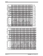
Страница 72: ... c i r P d e x i F y B l l e S B 6 6 1 0 0 1 4 2 0 7 2 d n e g e L E C I R P L A T O T 0 9 5 0 4 0 6 0 1 0 60mm x 44mm with Barcode BC 3000 B 0209D K Fmt 1 60mm x 44mm with Barcode BC 3000 B 0209D K Fmt 1 A6 Label Format Worksheets d l e i F n o i t c n u F d r a d n a t S e d o C e u l a V e u l a V d l O e u l a V w e N e z i S X h t d i W Y t h g i e H X h t d i W Y t h g i e H 8 2 1 e g a s s ...

Страница 73: ...tion of these fields also increases as do any data fields printed above the text d l e i F n o i t c n u F d r a d n a t S e d o C e u l a V e u l a V d l O e u l a V w e N e z i S X h t d i W Y t h g i e H X h t d i W Y t h g i e H 1 e d o c r a B 5 0 8 0 0 0 4 0 2 0 2 e t a D k c a P 3 0 2 6 1 0 7 4 2 0 3 e t a D n o i t a r i p x E 4 0 8 1 0 0 7 4 2 0 4 0 0 7 5 1 0 0 9 1 0 5 b l e c i r P t i n...

Страница 74: ...ata fields printed above the text d l e i F n o i t c n u F d r a d n a t S e d o C e u l a V e u l a V d l O e u l a V w e N e z i S X h t d i W Y t h g i e H X h t d i W Y t h g i e H 1 e d o c r a B 5 0 8 0 0 0 7 7 1 0 2 e t a D k c a P 3 0 2 6 1 0 8 2 2 0 3 e t a D n o i t a r i p x E 4 0 8 1 0 0 8 2 2 0 4 0 0 7 5 1 0 1 7 1 0 5 b l e c i r P t i n U 8 0 5 0 3 0 8 2 2 0 6 0 0 1 2 3 0 9 6 1 0 7 ...

Страница 75: ...xt d l e i F n o i t c n u F d r a d n a t S e d o C e u l a V e u l a V d l O e u l a V w e N e z i S X h t d i W Y t h g i e H X h t d i W Y t h g i e H 1 e t a D k c a P 3 0 8 0 0 0 1 4 1 0 2 e t a D n o i t a r i p x E 4 0 8 0 0 0 5 4 0 0 3 b l e c i r P t i n U 8 0 2 6 1 0 1 4 1 0 4 t h g i e W 9 0 7 9 2 0 1 4 1 0 5 e c i r P l a t o T 7 0 2 7 3 0 7 6 0 0 6 r e b m u N U L P 2 0 2 6 1 0 6 3 0...

Страница 76: ...tion use keys to select FIELD NUMBERS use key to select X Width or Y Height 60mm x 44mm UPC Barcode Label B 0312B d l e i F n o i t c n u F d r a d n a t S e d o C e u l a V e u l a V d l O e u l a V w e N X h t d i W Y t h g i e H X h t d i W Y t h g i e H 1 s s e r d d A e m a N e r o t S 1 0 8 0 0 0 5 6 4 0 2 n o i t p i r c s e D U L P 6 0 8 0 0 0 4 6 3 0 3 e d o c r a B 5 0 0 0 0 0 5 6 1 0 4 ...

Страница 77: ...tion use keys to select FIELD NUMBERS use key to select X Width or Y Height d l e i F n o i t c n u F d r a d n a t S e d o C e u l a V e u l a V d l O e u l a V w e N X h t d i W Y t h g i e H X h t d i W Y t h g i e H 1 s s e r d d A e m a N e r o t S 1 0 3 1 0 0 5 9 4 0 2 n o i t p i r c s e D U L P 6 0 6 1 0 0 4 9 3 0 3 e d o c r a B 5 0 8 0 0 0 4 0 2 0 4 e t a D k c a P 3 0 2 6 1 0 7 4 2 0 5 ...

Страница 78: ...L A T O T 0 9 5 1 4 0 6 5 1 0 5 2 1 e g a s s e M d A E 0 9 9 9 9 0 0 0 0 6 2 n g i S B 0 8 4 3 0 7 9 0 0 7 2 e c i r P l a t o T b u S 8 2 1 5 3 0 6 0 1 0 64mm x 85mm Safe Handling Label B 0312B d l e i F n o i t c n u F d r a d n a t S e d o C e u l a V e u l a V d l O e u l a V w e N X h t d i W Y t h g i e H X h t d i W Y t h g i e H 8 2 t h g i e W l a t o T b u S 7 2 8 9 3 0 8 5 2 0 9 2 s e ...

Страница 79: ... e S 3 6 9 9 9 9 1 4 2 0 6 2 D 8 9 9 9 9 1 4 2 0 7 2 e c i r P d e x i F y B l l e S B 6 9 9 9 9 1 4 2 0 64mm x 59mm Safe Handling Label B 0312B d l e i F n o i t c n u F d r a d n a t S e d o C e u l a V e u l a V d l O e u l a V w e N X h t d i W Y t h g i e H X h t d i W Y t h g i e H 8 2 d n e g e L E C I R P L A T O T 0 9 9 9 9 9 6 0 1 0 9 2 1 e g a s s e M d A E 0 9 9 9 9 0 0 0 0 0 3 n g i S...

Страница 80: ...Enter the Test Menu C00 Power ON holding the 1 key 2 Enter the Label Format step C07 00 7 ENTER 3 Select the label format 1 4 C07 01 format number PLU key 4 Enter Flag Change area C07 01 01 SIZE 5 Use the RIGHT ARROW to move across to column 17 decimal point location 6 Use the DOWN ARROW to move down to the Weight field refer to worksheets to determine Weight field number 7 Reduce the decimal poin...

Страница 81: ...IW512P1003 ISHIDA CO LTD 44 SANNO CHO SHOGOIN SAKYO KU KYOTO 606 JAPAN PHONE 075 771 4141 FACSIMILE 075 751 1634 TELEX 05422065 SCALES J CABLE ADD SCALES KYOTO ...

Отзывы: