Description of the drive module
Positioning module IMD20, IMD40
P2.0
GND 24V
Input
VCC
4K7
1
2
4K
7
10K
2K
2
3
4
TLP124
10NF
5
6
74HCT14SO
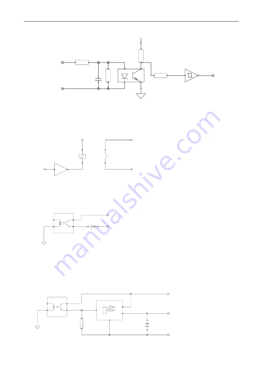
Digital output Ready
The Ready output is designed as a potential-free contact. It indicates the operational readiness of
the module and is only set, if the module software works correctly (monitoring through internal
watchdog timer). The design as a potential-free contact makes it possible to easily link several
Ready outputs. This sum signal can be processed e.g. in the safety circuit.
4
1
1
2
2
+24V
REL1
REL1
Ready In
Digital output Homing
The Homing output can be used to shunt the limit switch in the safety circuit. It is set during the
reference run (on limit switch).
3
Ready Out
DGND
1
2
3
4
K
A
1
2
TLP124
+24V
Output Homing
Digital output Brake
The Brake output is used for the brake control. The way in which the brake is controlled can be
defined by means of the software.
+24V
Ouput Brake
GND_24V
DGND
1
2
3
4
K
A
3
2
1
4
GND
IN
VBB
OUT
1
2
1
2
TLP124
10K
24


