9 Connectors and PIN assignments
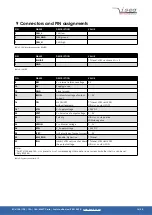
PIN
NAME
DESCRIPTION
VALUE
2
CAN_L
CAN low
3
CAN_GND
CAN ground
7
CAN_H
CAN high
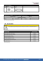
Table 3: CAN Interface connector (DSUB9)
PIN
NAME
DESCRIPTION
VALUE
1
INHIBIT
TTL level, LOW = active
➜
V
OUT
= 0
2
GND
Table 4: INHIBIT
PIN
NAME
DESCRIPTION
VALUE
8
REF
V
ref
Internal reference voltage
5 V
10
0V
Supply ground
12
GND
Signal ground
14
IMON
I
mon
Monitor voltage of output
current
0 .. 5 V
16
ON
HV ON/OFF
with voltage ramp
TTL-level, LOW
➜
HV ON
HIGH or n.c.
➜
HV OFF
18
(2
VIN
V
in
Supply voltage
+24 V DC
20
VSET
V
set
Set value of output voltage
0 .. 5 V
22
POL
Polarity
HIGH or n.c.
➜
positive
LOW
➜
negative
24
VMON
V
mon
Monitor voltage
0 .. 5 V
26
VIN
V
in
Supply voltage
+24 V DC
28
ISET
(1
I
set
Set voltage of output current 0 .. 5 V
30
KILL_ENA
Killenable, high active
TTL-level
32
INH
Inhibit, LOW = active, shut down
the output voltage
TTL-level, LOW
➜
HV OFF
HIGH or n.c.
➜
HV ON
Notes:
1)
For ECH 12A and 14A, I
set
is preset to I
nom
of corresponding HV-module, i.e. no current limit other that I
nom
can be set.
2)
Only ECH14A.
Table 5: System connector H15
ECH 124 / 128 / 12A / 14A - MMC Crate | Last modified on: 24.01.2020 | www.iseg-hv.com
16/20

