background image

4230-mmm & 4230-mmx.ib.rev4.doc 

Page 5 of 17

 17/10/2007


Configuration 


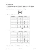
Link settings 


MMM-4230 CONFIGURATION INFORMATION 


Program 4230mmm.tdf

 LK6A 

Installed 

 
LK1  IN 

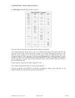
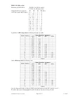
When using Switch 1 position A ‘Variable Bandwidth’, if the frequency of an input that has an 
assignment of 26.8Mb/s falls below 13.4Mb/s then the assignment will revert to 13.4Mb/s. All other 
conditions mentioned in the Variable Bandwidth section still apply. 


OUT  The frequency resetting mentioned above does not occur. 

 
LK2  IN 

Existing Reed Solomon encoding on ASI streams will pass through system. 


If no RS is present on the input then RS encoding is added.  


OUT  Reed Solomon encoding added to input ASI steams regardless of whether existing RS encoding exists 

or not. 

 
LK3 Not 

used. 

 
LK4

*

  IN 

Output G.703 signal will be “framed”. 

OUT  Output G.703 signal will be “unframed”. 

 
LK5

*

  IN 

Output “unshaped” (recommended for output drive lengths > 68m (225ft)). 


OUT  Output “shaped” (recommended for output drive lengths < 68m (225ft)). 

 
LK7 

Installing this link will terminate the RS-422 data line. 

 
Note:  * 

Not applicable for 34 Mb/s (E3) version. 


MMX-4230 CONFIGURATION INFORMATION 

 
LK1  IN 

Allows instantaneous changes in channel bandwidth allocation as required by the “Variable” Data 
Assignment. 


OUT  Error concealment is applied to the packet distribution. 

 
LK2  IN 

Output packet size is always 204 byte and will contain Reed Solomon code regardless of 
corresponding MMM-4230 input packet size. 


OUT  Output packet size matches that of corresponding MMM-4230 input packet size. 

 
LK3  IN 

Outputs can be individually disabled by SNMP remote control. Note that this requires SNMP 
functionality within IRT’s SNMP frame. 


OUT  All outputs are always enabled. SNMP functionality not required. 

 
LK4

*

  IN 

For input G.703 signal that is “framed”. 

OUT  For input G.703 signal that is not “framed”. 

 
LK5  IN 

Input G.703 equaliser not enabled. 


OUT  Input G.703 equaliser enabled. 

 
LK10 

Installing this link will terminate the RS-422 data line. 

 
Note:  * 

Not applicable for 34 Mb/s (E3) version. 

Содержание MMM-4230

Страница 1: ...R T Electronics Pty Ltd A B N 35 000 832 575 26 Hotham Parade ARTARMON N S W 2064 AUSTRALIA National Phone 02 9439 3744 Fax 02 9439 7439 International 61 2 9439 3744 61 2 9439 7439 Email sales irtele...

Страница 2: ...tenance Storage 16 Warranty Service 16 Equipment return 16 Drawing List Index 17 This instruction book applies to units later than S N 0504001 Operational Safety WARNING Operation of electronic equipm...

Страница 3: ...Belden 8281 or equivalent cable RS422 9600 Baud uni directional data may also be sent on the same link Front panel indication and relay alarm on the MMM 4230 transmitter shows if there is an input da...

Страница 4: ...istics B3ZS encoded Data Rate 44 736 Mb s Outputs Type 1 4 x ASI C 75 800 mVp p BNC connector Data Rate same as MMM 4230 input rate Type 2 RS 422 9600 Baud Uni directional Alarm Output Contact closure...

Страница 5: ...s 68m 225ft OUT Output shaped recommended for output drive lengths 68m 225ft LK7 Installing this link will terminate the RS 422 data line Note Not applicable for 34 Mb s E3 version MMX 4230 CONFIGURAT...

Страница 6: ...Position I P 1 I P 2 I P 3 I P 4 0 43 5 1 38 26 5 46 2 32 8 10 93 3 27 33 16 4 4 21 86 21 86 5 32 8 5 46 5 46 6 27 33 10 93 5 46 7 21 86 16 4 5 46 8 21 86 10 93 10 93 9 14 6 14 6 14 6 A Variable B 21...

Страница 7: ...ts 2 3 4 input 2 has priority over inputs 3 4 and input 3 has priority over input 4 So even if say channel 2 has an input rate above 13 4 Mb s and then input 1 s rate also increases above 13 4 Mb s th...

Страница 8: ...2 25 12 8 37 3 20 93 12 56 4 16 75 16 75 5 25 12 4 18 4 18 6 20 93 8 37 4 18 7 16 75 12 56 4 18 8 16 75 8 37 8 37 9 12 56 12 56 8 37 A 20 93 4 18 4 18 B 16 75 8 37 4 18 4 18 C 12 56 12 56 4 18 4 18 D...

Страница 9: ...connection Installation in frame or chassis See details in separate manual for selected frame type Signal Connections All ASI G 703 inputs and outputs are by 75 BNC connectors Alarm output is via a tw...

Страница 10: ...line up with the three sets of multipin sockets on the main PCB module Align all pins and then gently press the SMU 4000 all the way down into place If the SMU 4000 is not already programmed with the...

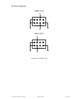
Страница 11: ...4230 mmm 4230 mmx ib rev4 doc Page 11 of 17 17 10 2007 RS 422 pin assignments Connectors viewed from top RB RA MMM 4230 TB TA MMX 4230...

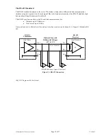
Страница 12: ...ces can be achieved The RS 422 specification allows reliable serial data communications for Distances up to 1200 metres Data rates of up to 10 Mb s Only one line driver is allowed on a line and up to...

Страница 13: ...bly drawings are not to scale and are intended to show connection order and approximate layout only G 703 OUT INPUT 1 INPUT 2 INPUT 3 RS 422 URGENT ALARM INPUT 4 G 703 IN OUTPUT 1 OUTPUT 2 OUTPUT 3 RS...

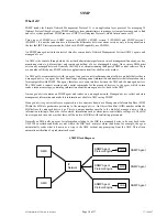
Страница 14: ...lates that information into a form compatible with SNMP The agent therefore acts as an interface between the NMS and the managed devices The NMS sends a request message and control commands for the ma...

Страница 15: ...ible need a plug in SMU 4000 module with a program relevant to the module that it is plugged into Depending on the module besides the module identification parameters such as alarm states inputs and c...

Страница 16: ...l be extended by IRT only to the extent obtainable from the component supplier Equipment return Before arranging service ensure that the fault is in the unit to be serviced and not in associated equip...

Страница 17: ...t 1 804900 2 MMM 4230 4 Channel ASI to G 703 Multiplexer Schematic sheet 2 804900 3 MMM 4230 4 Channel ASI to G 703 Multiplexer Schematic sheet 3 804902 1 MMX 4230 G 703 to 4 Channel ASI De Multiplexe...

Страница 18: ...IN 1 CHB_IN 0 CHB_CKR CHB_REF_CLK CHB_PRES R65 10K CD20 10uF CD57 0 1uF CD53 0 1uF CD52 0 1uF CHC_IN 8 CHC_IN 9 INA 1 INA 2 A B 3 BISTEN 4 INB 28 INB 27 MODE 26 REFCLK 25 RF 5 GND 6 RDY 7 GND 8 Vccn 9...

Страница 19: ...VCCINT 152 TDI 153 nCE 154 DCLK 155 DATA0 156 U1 EPF1K50QC208 3 VccINT VccIO R44 1K R30 1K VccIO CHA_PRES CHC_PRES CHA_IN 9 CHA_IN 8 CHA_IN 7 CHA_IN 6 CHA_IN 5 CHA_IN 4 CHA_IN 3 CHA_IN 2 CHA_IN 1 CHA_...

Страница 20: ...5V INPUT 1 COMMON 2 OUTPUT 3 U17 REG_LM3940 ADJUST 1 OUTPUT 2 INPUT 3 U16 LM317S 1 2 J5 RS422 RB RS422 RA SK1 Input 1 ASI INPUT 1 SK2 ASI INPUT 2 SK4 ASI INPUT 3 L9 0 022uH SK5 BNC G703 OUTPUT Input...

Страница 21: ...5Vb CHC_D7 CHC_SVS Output 4 CHC_D6 CHC_D5 CHC_D4 CHC_D3 CHC_D2 CHC_D1 CHC_D0 CHC_SC D CHC_CKW CHC_ENA OutB 1 OutC 2 OutC 3 Vccn 4 OutB 28 OutA 27 OutA 26 FOTO 25 BISTEN 5 GND 6 MODE 7 RP 8 Vccq 9 SVS...

Страница 22: ...NDINT 129 VCCINT 130 131 132 133 134 135 136 GNDINT 137 VCCIO 138 139 140 141 142 143 144 GNDINT 145 VCCIO 146 147 148 149 150 GNDINT 151 VCCINT 152 TDI 153 nCE 154 DCLK 155 DATA0 156 U1 EPF1K50QC208...

Страница 23: ...A L5 0 015uH SK1 ASI OUTPUT 1 L6 0 015uH SK2 ASI OUTPUT 2 L8 0 015uH SK4 ASI OUTPUT 4 L9 0 022uH SK5 BNC INPUT Output3 Output4 G7039in URGENT ALARM R54 R 5VB URGENT RELAY RL1 COIL 5V RL1 CONTACT R43 4...

Отзывы: