background image

Solar Mounting Made Simple

R

Light Rail

Installation Manual

Page 4 


   |     

ironridge.com

     |     (800) 227-9523

  2013 v1.3  


support@

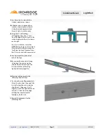
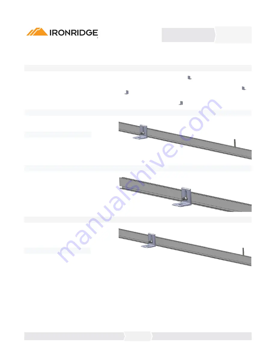
A.

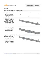
 Mount all of the feet to the roof 

     in the desired locations.


Note:


Determine the maximum

      distance between feet according

      to engineering specifications.

Assembly

Step 1. Mounting the feet and the first piece of rail.

Step 2. Mounting the next pieces of rail.

B.

 On the next piece of rail, slide

     3/8-16” bolts into the side facing

     t-slot on the rail. Space the bolts

     out to match the foot spacing.

B.

 On the first piece of rail, slide

     3/8-16” bolts into the side facing

     t-slot on the rail. Space the bolts

     out to match the foot spacing.

D.

 Attach this first piece of rail to the 

     feet mounted on the roof. Mount
     the rail to each foot with a flange
     nut and hex bolt. Hand tighten 
     the nuts and check the level of 
     the rail. Tighten 3/8-16 hardware
     to 236 in-lbs.

C.

 On this same piece of rail, slide 

     1/4-20”  bolts into the top facing 

     t-slot on the rail. Space the bolts 

     out to match the panel spacing.

C.

 On this same piece of rail, slide 

     1/4-20”  bolts into the top facing 

     t-slot on the rail. Space the bolts 

     out to match the panel spacing.
Содержание XRL Light Rail

Страница 1: ...Installation Manual A complete Manual for the installation of IronRidge s Light Rail system Solar Mounting Made Simple R Roof Mounting System 2013 Edition v1 3 Light Rail XRL ...

Страница 2: ...assembly of the IronRidge Light Rail Mounting System TOC ironridge com 800 227 9523 2013 v1 3 support Table of Contents Installation Manual Customer Support Tools Required For Assembly Torque Values For Dry Bolts Component List Assembly Step 1 5 Assembly Step 2 6 Assembly Step 3 7 Assembly Step 3 8 Warranty Information 9 Assembly Step 2 Grounding Setup 4 ...

Страница 3: ...of appropriate flashing vii Ensuring safe installation of all electrical aspects of the PV array and viii Ensuring that PV module is UL or CE listed and verification of PV Module s capacity to support the loads associated with the given array and ix Ensuring correct and appropriate design parameters are used in determining the design loading used for the specific installation Parameters such as sn...

Страница 4: ...stallation manual for IronRidge Light and Standard Series Rail for proper installation procedures Mm Inches Clamp Type Bolt Height End Clamp Mid Clamp hex Mid Clamp tbolt 31 0 32 5 1 22 1 28 I 2 00 29 7000 125 29 7000 105 29 70TB 105 33 3 34 8 1 31 1 37 A 2 00 29 7000 134 29 7000 105 29 70TB 105 34 8 36 8 1 37 1 45 B 2 00 29 7000 224 29 7000 105 29 70TB 105 39 0 41 0 1 53 1 61 C 2 25 29 7000 157 2...

Страница 5: ...he anchor point for the rest of the panel assembly Light Rail Attaches to the foot via foot clamp and provides support for the PV modules Mid Clamp Clamps the inside edges of the PV modules to the rails Internal Splice Ties the extrusion rails together extending their length End Clamp Clamps the outside ends of the PV modules to the rails End Cap Caps off the end of the rail and prevents the colle...

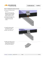
Страница 6: ...the bolts out to match the foot spacing B On the first piece of rail slide 3 8 16 bolts into the side facing t slot on the rail Space the bolts out to match the foot spacing D Attach this first piece of rail to the feet mounted on the roof Mount the rail to each foot with a flange nut and hex bolt Hand tighten the nuts and check the level of the rail Tighten 3 8 16 hardware to 236 in lbs C On this...

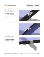
Страница 7: ...d evenly together H Maintain rail alignment while following the next steps I You should mark off approximately three 3 inches from the end of the first rail where the internal splice should end Drive one 1 self tapping screws through the second rail one 1 inch from the edge utilizing the same horizontal location as the first rail E Using one 1 self drilling self tapping screw one 1 inch from the e...

Страница 8: ...Wiley Burndy installation manual for IronRidge Light and Standard Series Rails for proper installation procedures C Complete the clamp assembly with a flange nut as shown Tighten end clamp to 65 in lbs D Repeat with the other clamp E Working from the opposite side of the PV module Assemble the mid clamps by putting a clamp on the bolt followed by the flange nut B Then slip the end clamp over the b...

Страница 9: ...tact with the edges of both panels Note For installations that utilize WEEBs please refer to Wiley Burndy installation manual for IronRidge Light and Standard Series Rails for proper installation procedures G Tighten to 120 in lbs dry 100 in lbs wet H Repeat the procedure using mid clamps to secure each successive module I Secure the last module at the end of the rails using the other set of end c...

Страница 10: ...followed by Purchaser for IronRidge s galvanized steel based components The warranties above do not cover any parts or materials not manufactured by IronRidge and exclude nonfunctionally related defects as defined solely by IronRidge The warranties do not cover any defect that has not been reported to IronRidge in writing within twenty 20 days after discovery of such defect In the event of breach ...

Отзывы: