


14
Copyright 2021 Iron Bow Technologies
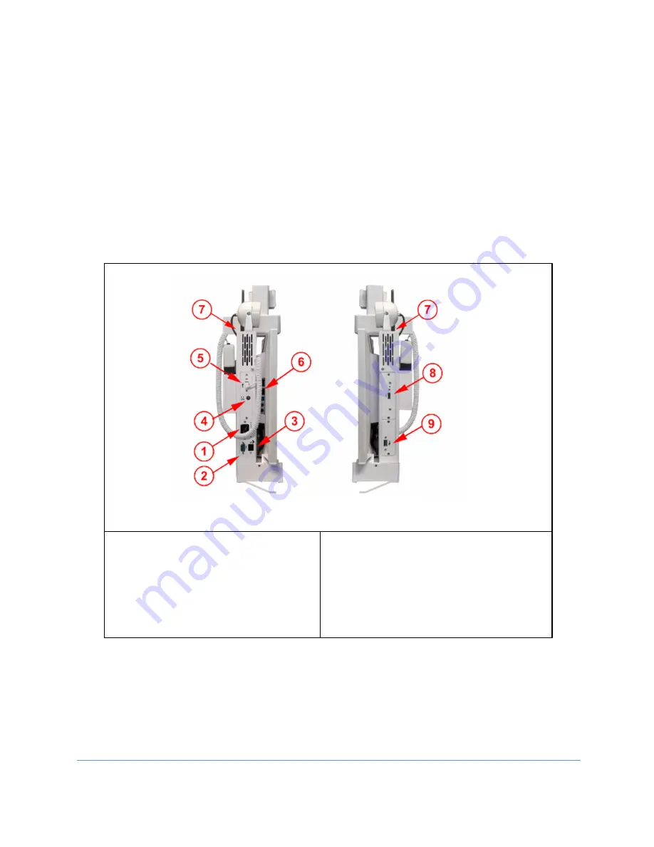
Connections
The Vidyo CLINiC includes an AC power inlet, an Ethernet port for connecting to a wired
network, two USB 3 ports for connecting the system controller plus an external
examination device, such as a Horus Scope and an HDMI Video Input for connection of
an external PC.
If it is necessary to attach a standard PC keyboard/mouse for system set up, the two USB 3
ports designated for the controller and a Horus Scope, can be utilized for connection of
these devices. Once set up has been completed, the keyboard/mouse should be
disconnected and the system controller and Horus Scope re-connected. The system should
then be power cycled to ensure correct operation.
1.
IEC Main power inlet
2.
DB9 Expansion control port (for
future use)
3.
10/100/1G Ethernet port
4.
Electronic Stethoscope Input
5.
Controller USB 3 port
6.
Display ports (for future use)
7.
2 x Wi-Fi Antenna ports
8.
HDMI Video Input (PC Usage)
9.
USB 3 Port (Horus Scope Input)
Left Side View Right Side View
Figure 12- System Connection Ports


