IRO 1131 CAN plus Скачать руководство пользователя страница 4

3

Ref. No. 31-8931-0201-06/0536

1131 CAN plus  

Installation/ Mains Connection
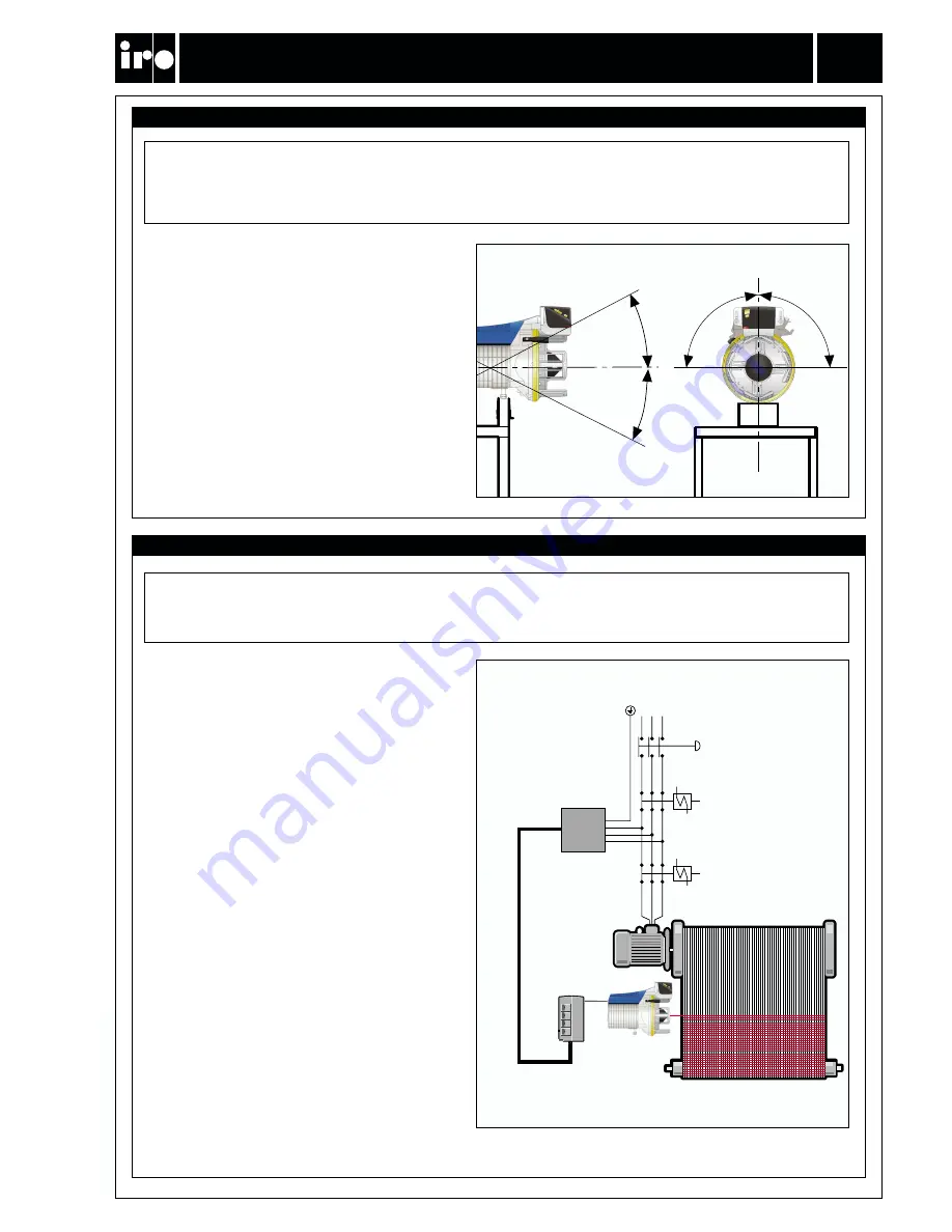
L2

L1

L3

PE

Feeders must be mounted within 40° of the

horizontal plane.

40°

40°

90°

90°

IMPORTANT!

Turn off the main switch before any work is carried out on the electrical circuit. 

Mains supply

Main switch

Emergency stop

Installation

Mains connection

The power supply to the feeder must not be

disrupted when the weaving machine stops.

NOTE

Condensation can form on the weft feeder when it is moved from the cold environment of the warehouse

to the warmer environment of the loom room. Make sure that the feeder is dry before switching it on.

Power supply

Содержание 1131 CAN plus

Страница 1: ...1131 CAN plus Operating Instructions Ref No 31 8931 0201 06 0536 IRO AB Box 54 SE 523 22 Ulricehamn Sweden Tel Int 46 321 29700 Fax Int 46 321 29800 www iroab com info iro se GB English ...

Страница 2: ...perating diagram 4 Main parts 5 System orientation 6 Settings 7 N R rotation Yarn separation 8 Balloon control Threading 9 Rotating the spool body 10 Maintenance 11 Fault finding 12 13 IRO AB RESERVE THE RIGHT TO CHANGE THE CONTENTS OF THE USER S GUIDE AND TECHNICAL SPECIFICATIONS WITHOUT PRIOR NOTIFICATION Contents ...

Страница 3: ...L COMPONENTS THE FEEDER AND THE TRANSFORMER CABINET MUST BE FULLY ASSEMBLED BEFORE THE POWER SUPPLY IS CONNECTED THE FEEDER AND TRANSFORMER CONTAIN ELECTRICAL COMPONENTS THAT RETAIN AN ELECTRIC CURRENT UP TO THREE MINUTES AFTER DISCONNECTION ALL WORK ON ELECTRICAL COMPONENTS MUST BE CARRIED OUT BY A QUALIFIED ELECTRICIAN THIS PRODUCT IS NOT INTENDED FOR USE IN POTENTIALLY EXPLOSIVE ATMOSPHERES OR ...

Страница 4: ... carried out on the electrical circuit Mains supply Main switch Emergency stop Installation Mains connection The power supply to the feeder must not be disrupted when the weaving machine stops NOTE Condensation can form on the weft feeder when it is moved from the cold environment of the warehouse to the warmer environment of the loom room Make sure that the feeder is dry before switching it on Po...

Страница 5: ...4 Ref No 31 8931 0201 06 0536 1131 CAN plus Operating Diagram Operating diagram 290V Dc 26V Dc TB1 TB2 Motor Accessories Interface extension 12 colour Signal Motor control unit Extension Interface ...

Страница 6: ...ensor Magnet release button On Off switch 5 Ref No 31 8931 0201 06 0536 1131 CAN plus Main Parts Signal lamp Pneumatic threading PTU Stopper unit Magnet finger Fixed finger Winding disc Yarn transport finger Side view Front view ...

Страница 7: ...erminal and transmitted to the feeder through the CAN bus For precise yarn release the feeders are connected to the machines angle bus encoder The brushless permanent magnet motor is controlled from the control board situated under the top cover At feeder start up the number of windings on the spool body is controlled by the yarn store sensor which indicates the outer limit of the yarn store The n...

Страница 8: ... 06 0536 1131 CAN plus Settings Stopper unit positioning screws Finger adjustment guide 0 5 1 0 mm Position of eyelet Move the stopper unit to its uppermost position before any adjustments are carried out Adjust each finger in turn first the fixed finger then the yarn transport finger Only loosen the locating screws sufficiently to move the finger excessive loosening gives faulty values When adjus...

Страница 9: ...versed rotation in an anti clockwise direction The more the winding disc is rotated the larger will be the yarn separation 4 Point B on the front plate is the reference point for adjusting separation When point C is aligned with B the yarn separation is set at zero By aligning D or E with B the yarn separation is set at maximum Note excessive yarn separation can cause inferior weaving results and ...

Страница 10: ...l body To do this the magnet pin must be opened This can be performed using any of the following methods 1 A short push on the yarn release button will release one winding 2 By pushing the yarn release button and keeping it pushed in the magnet pin will remain open as long as the button is pushed in After the magnet pin has been opened any yarn on the spool body can be removed To thread the unit p...

Страница 11: ...power to the weaving machine is switched off Remove the two screws retaining the stopper housing Remove the stopper housing completely The spool body can now be rotated as necessary When reassembling the stopper housing it will be necessary to adjust the distance between the magnet and the magnet finger using the guide see page 7 Rotating the spool body Balloon control Rotating the spool body WARN...

Страница 12: ...lus Maintenace It is recommended to carry out a periodical cleaning of any lint or dust accumulation on the feeder or the control box The unit requires no extra lubrication IMPORTANT The connector cover must be assembled min 20 cm Maintenance ...

Страница 13: ...ble function Stopper magnet connector Coil resistance Yellow Blue 65 Ohm Red Green 65 Ohm Motor connector Coil resistance Yellow Red 8 Ohm Yellow Green 8 Ohm Green Red 8 Ohm Voltage check Interface check Feeder check Code switch settings CAN enabled Fuse T5A 250 V 24V DC for feeder and communication feeder size Fuse T3 15A 500V 290V DC feeder motor Fuse T0 75A 250V 24V DC for communication loom si...

Страница 14: ...ted to the circuit board 8 Sensor board not connected Check that the sensor board connector is proberly connected to the circuit board 9 Motor not connected Check that the motor connector is properly connected to the circuit board 10 Wrong reserve sensor settings Adjust sensor sensitivity settings loom terminal 11 Wrong winding sensor settings Adjust sensor sensitivity settings loom terminal 12 Wr...

Отзывы: