background image

13

RCM-26 Remote Control Module

Owner’s Manual

monitoring of input or output signals of all power amps in the remote network,
without the need for additional wiring. Nominal output level is +6 dBu (1.55 V)
and maximum output level is +21 dBu (8.7 V). 

The CAN bus allows using different data rates, whereas the data rate is
inversely proportional to the bus length. For smaller network setups, data rates
can be as high as 500 kbit/s. For broader networks, reducing the data rate
becomes necessary (down to the minimum data rate of 10 kbit/s). 

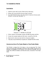
The following table illustrates the relation between data rate and bus length or
network size. The use of CAN repeaters is strongly recommended for busses
that exceed 1000 meters in length.

NOTE: 
The data rate of the CAN Bus is preset to 10 kbit/s.

Transfer rate (in kbit/s) Bus length (in m)

500

100

250

250

125

500

62,5

1000

20

2500

10

5000

Tabelle 2.1: Transfer rate and bus length

Illustration 2.3: Pin-assignment of CAN jack

Illustration 2.4: Pin-assignment of CAN plug

Содержание RCM-26

Страница 1: ...OWNER S MANUAL BEDIENUNGSANLEITUNG MODE D EMPLOI RCM 26 Remote Control Module ...

Страница 2: ...ch 14 7 CONTROL PORT 16 8 RS 232 Interface 16 CAN Bus Principles 18 System Examples 19 Performance Specifications 20 INHALT Einleitung 27 Systembeschreibung 27 Auspacken Garantie 28 Installationshinweise 29 Einbau 29 Umbau von Pre Fader auf Post Fader Betriebsart 29 IRIS Net 30 Bedienelemente und Anschlüsse 32 1 AES EBU IN 32 2 AES EBU OUT 33 3 LOCK LED 33 4 REMOTE CAN BUS Anschlüsse 33 5 STATUS L...

Страница 3: ... 51 IRIS Net 52 Commandes et connexions 54 1 AES EBU IN 54 2 AES EBU OUT 55 3 Témoin LOCK 56 4 Connexion REMOTE CAN BUS 56 5 Témoin STATUS 58 6 Sélecteurs ADDRESS 58 7 PORT DE CONTROLE 60 8 Interface RS 232 60 Principes du Bus CAN 62 Exemples de systèmes 64 Caractéristiques des Performances 65 Appendix 68 Specifications Technische Daten 68 Block Diagram Blockschaltbild 71 Dimensions Abmessungen 72...

Страница 4: ...sold with the apparatus When a cart is used use caution when moving the cart apparatus combination to avoid injury from tip over 13 Unplug this apparatus during lightning storms or when unused for a long period of time 14 Refer all servicing to qualified service personnel Servicing is required when the apparatus has been damaged in any way such as power supply cord or plug is damaged liquid has be...

Страница 5: ...ll times The minimum distance between parts carrying mains voltage and any switches or breakers that are not connected to the mains secondary parts has to be 6 mm and needs to be minded at all times 5 Replacing special components that are marked in the circuit diagram using the security symbol Note is only permissible when using original parts 6 Altering the circuitry without prior consent or advi...

Страница 6: ...omatic reaction when specific thresholds are being exceeded or fallen below is also possible With an RCM 26 installed the integrated impedance testing function allows very precise monitoring of the connected loudspeaker systems The impedance testing function utilizes the internal test tone signal generator and voltage current measuring to determine the impedance of the loudspeaker systems includin...

Страница 7: ...tal audio input with XLR type connector are provided The use of the digital audio input offers a dynamic range of 128 dB Using the analog audio input offers a dynamic range of 120 dB which by the way is an absolute peak value for digital audio devices For further details about configuration control and monitoring of amps with installed RCM 26 modules please refer to the documentation of the IRIS N...

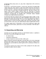
Страница 8: ...ect the needed interfaces CAN Audio Control Port RS 232 6 Reconnect the mains cord and switch on the power amplifier 7 The power amp automatically recognizes the installed RCM 26 module Conversion from Pre Fader Mode to Post Fader Mode The RCM 26 is shipped from the factory in the recommended Pre Fader mode so the input level controllers on the front of the amplifier are taken out of operation by ...

Страница 9: ...ip conducter of the top and middle contact of each JP1 to JP5 has to be cut 2 A link has to be soldered between the middle and lower contact of each JP1 to JP5 1 4 IRIS Net Configuring and controlling a remote amplifier with a RCM 26 module installed is possible through the use of IRIS Net Intelligent Remote Integrated Supervision PC software IRIS Net allows programming the RCM 26 module s complet...

Страница 10: ...er s Manual The following illustrations show an example of a power amplifier system in IRIS Net and the DSP flow chart of a RCM 26 Illustration 1 3 Power amplifier system with User Controls Illustration 1 4 DSP flow diagram of the RCM 26 ...

Страница 11: ...connector The AES EBU input is a balanced transformer isolated input A sampling rate converter translates the input signal to match the internal sampling rate However the possibility to synchronize the RCM 26 to an external sampling rate exists as well For further details please refer to the IRIS Net help files The following illustration shows the pin assignment of the input socket Illustration 2 ...

Страница 12: ...ith no digital audio signal being present at the input or the internal PLL not having locked on to the incoming signal The audio signal gets muted when the digital input has been selected 4 REMOTE CAN BUS Connection The RCM 26 module provides two Neutrik EtherCon RJ 45 sockets for connecting to the REMOTE CAN BUS These sockets are connected in parallel and serve as inputs as well as for daisy chai...

Страница 13: ...n be as high as 500 kbit s For broader networks reducing the data rate becomes necessary down to the minimum data rate of 10 kbit s The following table illustrates the relation between data rate and bus length or network size The use of CAN repeaters is strongly recommended for busses that exceed 1000 meters in length NOTE The data rate of the CAN Bus is preset to 10 kbit s Transfer rate in kbit s...

Страница 14: ...tion on the CAN bus is recognized the LED lights for at least 100 ms when the power amplifier sends data on the CAN bus 6 ADDRESS Selector Switch The two address selector switches are for setting the network address of the RCM 26 CAN networks support addresses in the range of 01 to 250 FA hex Addressing has to be carried out in the hexadecimal number system The LOW selector switch sets the lower d...

Страница 15: ...t appear in the system even though it is physically connected to the CAN bus HIGH LOW Address 0 0 Stand alone 0 1 F 1 15 1 0 F 16 31 2 0 F 32 47 3 0 F 48 63 4 0 F 64 79 5 0 F 80 95 6 0 F 96 111 7 0 F 112 127 8 0 F 128 143 9 0 F 144 159 A 0 F 160 175 B 0 F 176 191 C 0 F 192 207 D 0 F 208 223 E 0 F 224 239 F 0 A 240 250 F B F reserved Tabelle 2 3 CAN addresses ...

Страница 16: ...ound The control outputs are configurable via IRIS Net and are used to signal internal states LEDs indicators or relays can be driven directly The 5V reference connector provides voltage supply for connected components 8 RS 232 Interface The RS 232 interface is for interconnecting the RCM 26 module and multi media control systems or facility management systems All parameters can be controlled and ...

Страница 17: ...s of the RCM 26 s RS 232 interface The connected device e g a PC with terminal program multi media control software needs to be identically configured for data transfer to work properly Parameter Value Data bit 8 Parity bit Stop bit 1 Transfer rate 19200 bit s Table 2 4 Parameter of RS 232 Interface ...

Страница 18: ...esistor value is used network errors can occur as a signal is reflected on the bus at both bus ends Because of the superposition of the reflection with the original signal the original signal is blurred This may result in the loss of data In order to prevent or minimize reflections at the bus ends terminators are used as they absorb the energy of the signal Since the CAN interfaces of all EVI Audi...

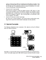
Страница 19: ...accomplishes a signal processing and a reinforcement of the bus signals The internal running time of the repeaters of approx 150 ns corresponds to an extension of the bus over approx 45 meters Creation of alternative network topologies By using one or several repeaters not only the above mentioned bus topo logy but the creation of other network topologies are also possible 3 1 System Examples The ...

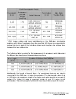
Страница 20: ...a CAN bus need to be terminated with 120 Ω termination plugs The maximum bus length depends on the actual data transfer rate the kind of data transfer cable being used as well as the total number of participants on the bus The following table shows the most essential requirements for CAN networks consisting of up to 64 participants Illustration 3 3 System with 2 amp racks and 1 USB CAN Converter T...

Страница 21: ...up to 125 kbit s the maximum length of a single stub cable should not exceed 2 meters For higher bit rates a maximum length of only 0 3 meter is still permissible The entire length of all branch lines should not exceed 30 meters Bus Length in m Data Transmission Cable Termination in Ω Max Data Transfer Rate Resistance per Unit Length in mΩ m Cable Diameter 0 40 70 0 25 0 34 mm AWG23 AWG22 124 1000...

Страница 22: ...are concerned common RJ 45 patch cables with a characteristic impedance of 100 Ω AWG 24 AWG 26 can be used for the cabling inside of a rack mounted system The previously outlined guidelines for network cabling are mandatory as far as the rack mounted shelve interconnection or fixed installations are involved ...

Страница 23: ...BEDIENUNGSANLEITUNG RCM 26 Remote Control Module ...

Страница 24: ...RIS Net 30 Bedienelemente und Anschlüsse 32 1 AES EBU IN 32 2 AES EBU OUT 33 3 LOCK LED 33 4 REMOTE CAN BUS Anschlüsse 33 5 STATUS LED 35 6 ADDRESS Wahlschalter 35 7 CONTROL PORT 37 8 RS 232 Schnittstelle 37 Remote Control Netzwerk 39 Systembeispiele 41 Leitungsspezifikation 42 Appendix 68 Specifications Technische Daten 68 Block Diagram Blockschaltbild 71 Dimensions Abmessungen 72 ...

Страница 25: ...r 13 Überlassen Sie sämtliche Servicearbeiten und Reparaturen einem ausgebildeten Kundendiensttechniker Servicearbeiten sind notwendig sobald das Gerät auf irgendeine Weise beschädigt wurde wie z B eine Beschädigung des Netzkabels oder des Netzsteckers wenn eine Flüssigkeit in das Gerät geschüttet wurde oder ein Gegenstand in das Gerät gefallen ist wenn das Gerät Regen oder Feuchtigkeit ausgesetzt...

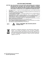
Страница 26: ... Metallgehäuse bzw zwischen den Netzpolen betragen 3 mm und sind unbedingt einzuhalten 5 Die Mindestabstände zwischen netzspannungsführenden Teilen und Schaltungsteilen die nicht mit dem Netz verbunden sind sekundär betragen 6 mm und sind unbedingt einzuhalten 6 Spezielle Bauteile die im Stromlaufplan mit dem Sicherheitssymbol gekennzeichnet sind Note dürfen nur durch Originalteile ersetzt werden ...

Страница 27: ...werden Eine automatische Reaktion bei Über oder Unterschreitung be stimmter Grenzwerte ist ebenfalls programmierbar Der Einbau eines RCM 26 ermöglicht durch die integrierte Impedanz Messfunktion eine wesentlich genauere Überprüfung der angeschlossenen Lautsprecher Die Impedanz Messfunktion bestimmt mit Hilfe des internen Signal Generators und der Strom Spannungsmessung die Impedanz der Laut sprech...

Страница 28: ...t Es stehen sowohl analoge Audioeingänge intern mit Pre Post Fader Umschaltung als auch ein AES3 AES EBU Digital Audioeingang mit XLR Buchse zur Verfügung Bei Verwendung des digitalen Audioeingangs beträgt die Dynamik 128 dB Der analoge Audioeingang erreicht eine Dynamik von 120 dB ebenfalls ein absoluter Spitzenwert für digitale Audiogeräte Sämtliche Details zur Konfiguration Steuerung und Überwa...

Страница 29: ...AN Audio Control Port RS 232 6 Netzkabel in Endstufe einstecken und Endstufe einschalten 7 Das RCM 26 Modul wird in der Endstufe automatisch erkannt Umbau von Pre Fader auf Post Fader Betriebsart Das RCM 26 befindet sich ab Werk in der empfohlenen Pre Fader Betriebsart die Eingangspegel Regler der Endstufe werden also durch Einbau des RCM 26 außer Betrieb genommen Sollen die Eingangspegel Regler b...

Страница 30: ...orgfältig durchtrennt werden 2 Zwischen dem mittleren und unteren Kontakt der JP1 bis JP5 muss jeweils eine Drahtbrücke eingelötet werden 1 4 IRIS Net Zur Konfiguration und Bedienung eines Remote Amplifiers mit RCM 26 wird die PC Software IRIS Net Intelligent Remote Integrated Supervision verwendet Die gesamte Konfiguration des RCM 26 kann hierbei offline auf dem PC erstellt werden In den Hilfe Da...

Страница 31: ...31 RCM 26 Remote Control Module Bedienungsanleitung Abbildung 1 3 Endstufensystem in IRIS Net mit Bedienelementen Abbildung 1 4 DSP Flussgraph des RCM 26 ...

Страница 32: ...ngeschlossen Es handelt sich um einen symmetrischen Eingang mit Übertrager zur galvanischen Isolierung Über einen Sample Rate Converter wird das Signal an die interne Abtastrate angepasst Es besteht aber auch die Möglichkeit das RCM 26 auf die externe Abtastrate zu synchronisieren Details hierzu finden Sie in den Hilfe Dateien von IRIS Net Folgende Abbildung zeigt die Belegung der Eingangsbuchse A...

Страница 33: ...U Eingang auf das empfangene Signal synchronisiert ist und die Audioübertragung in Ordnung ist Wenn die LOCK LED nicht leuchtet liegt entweder kein digitales Audiosignal an oder die interne PLL ist nicht auf das ankommende Signal eingerastet Falls der Digital Eingang gewählt ist wird das Audiosignal in diesem Fall stumm geschaltet 4 REMOTE CAN BUS Anschlüsse Das RCM 26 Modul besitzt zwei Neutrik E...

Страница 34: ...tenraten wobei die Datenrate indirekt proportional zur Buslänge ist Wenn das Netzwerk nur eine geringe Ausdehnung hat sind Datenraten bis zu 500 kbit s möglich Bei größeren Ausdehnungen muss die Datenrate herab gesetzt werden bis zur minimalen Datenrate von 10 kbit s Die folgende Tabelle erläutert den Zusammenhang zwischen Datenrate und Buslänge bzw Netzwerkausdehnung Buslängen über 1000 Meter sol...

Страница 35: ...auf Sobald eine Kommunikation am CAN Bus erkannt wurde wird die LED immer dann für mindestens 100 ms aktiviert wenn die Endstufe selbst Daten auf den CAN Bus sendet 6 ADDRESS Wahlschalter Mit den beiden ADDRESS Wahlschaltern wird die Netzwerk Adresse des RCM 26 eingestellt In einem CAN Netzwerk können die Adressen 01 bis 250 FA hex verwendet werden Die Adresseinstellung erfolgt im hexadezimalen Za...

Страница 36: ...ist Das Modul erscheint somit nicht im System auch wenn es am CAN Bus angesteckt ist ACHTUNG Jede Adresse darf im System nur einmal vorkommen da es sonst zu Netzwerk Konflikten kommt HIGH LOW Adresse 0 0 Stand alone 0 1 F 1 15 1 0 F 16 31 2 0 F 32 47 3 0 F 48 63 4 0 F 64 79 5 0 F 80 95 6 0 F 96 111 7 0 F 112 127 8 0 F 128 143 9 0 F 144 159 A 0 F 160 175 B 0 F 176 191 C 0 F 192 207 D 0 F 208 223 E ...

Страница 37: ...nd On sind die Ausgänge gegen Masse geschlossen Die Steuerausgänge werden über IRIS Net konfiguriert und dienen zur Signalisierung interner Zustände LEDs Kontrollleuchten oder Relais können direkt angesteuert werden Der 5V Refe renzanschluss dient zur Versorgung der extern angeschlossenen Elemente 8 RS 232 Schnittstelle Die RS 232 Schnittstelle dient der Verbindung des RCM 26 mit Mediensteuerungss...

Страница 38: ...e feste Werkseinstellung die in folgender Tabelle angegeben ist Ein angeschlossenes Gerät z B PC mit Terminalprogramm Mediensteuerung muss identisch konfiguriert sein damit eine Datenübertragung möglich ist Abbildung 2 5 Belegung der RS 232 Schnittstelle Parameter Wert Datenbits 8 Paritybit Stoppbit 1 Geschwindigkeit 19200 bit s Tabelle 2 4 Parameter der RS 232 Schnittstelle ...

Страница 39: ...ossen werden Der CAN Bus muss an beiden Enden mit einem 120 Ω Abschlusswiderstand terminiert werden Bei fehlender oder falscher Terminierung können Funktions störungen auftreten da ein Signal auf einem Bus an beiden Bus Enden reflek tiert wird Durch Überlagerung der Reflexionen mit dem ursprünglichen Signal wird dieses verzerrt was zu Datenverlusten führen kann Zur Verhinderung oder Minimierung vo...

Страница 40: ... folgt aus dem verwendeten Adressierungs schema des CAN Busses dieses erlaubt die Vergabe von höchstens 250 unterschiedlichen CAN Geräteadressen Verbesserung der Signalqualität auf dem CAN BUS Bei CAN Bus Systemen deren Buslänge 1000 Meter überschreitet sollte ein CAN Bus Repeater verwendet werden Der CAN Bus Repeater führt eine Aufbereitung und Verstärkung der Bussignale durch Die dabei auftre te...

Страница 41: ...le von Systemverdrahtungen eines Remote Control Netzwerks Zur Verbindung des Remote Control Netz werks mit einem PC wird jeweils ein USB CAN Converter verwendet Abbildung 3 2 5 Remote Amplifier mit RCM 26 und ein USB CAN Converter am Bus Anfang Abschluss Stecker am USB CAN Converter und am RCM 26 des Remote Amplifier 5 ...

Страница 42: ...t mit einem Wellenwiderstand von 120 Ω zum Einsatz kommen Als Leitungsabschluss muss an beiden Enden ein Abschlusswiderstand von 120 Ω vorgesehen werden Die maximale Buslänge ist abhängig von der Datenüber tragungsrate von der Art des Datenübertragungskabels sowie von der Anzahl Abbildung 3 3 System mit 2 Racks und einem USB CAN Converter Abschluss Stecker am Remote Amplifier 6 Bus Anfang und Remo...

Страница 43: ...AN Bus angeschlossen werden kann muss eine Stichleitung Abzweigleitung verwendet werden Da an einem CAN Bus immer genau zwei Abschlusswiderstände vorhanden sein müssen kann eine Stichleitung nicht terminiert sein Dadurch entstehen wiederum Buslänge in m Datenübertragungskabel Abschlusswi derstand in Ω Max Datenübertra gungsrate Widerstands belag in mΩ m Kabelquerschnitt 0 40 70 0 25 0 34 mm AWG23 ...

Страница 44: ... max 0 3 Meter nicht überschreiten Die Gesamtlänge aller Abzweigleitungen sollte 30 Meter nicht übersteigen Grundsätzlich gilt Für die Rack Verdrahtung können handelsübliche RJ 45 Patchkabel mit 100 Ω Wellenwiderstand verwendet werden AWG 24 AWG 26 wenn es sich nur um kurze Strecken handelt bis zu 10 Meter Für die Verdrahtung der Racks untereinander und in der Gebäudeinstalla tion sind unbedingt d...

Страница 45: ...MODE D EMPLOI RCM 26 Remote Control Module ...

Страница 46: ... 51 IRIS Net 52 Commandes et connexions 54 1 AES EBU IN 54 2 AES EBU OUT 55 3 Témoin LOCK 56 4 Connexion REMOTE CAN BUS 56 5 Témoin STATUS 58 6 Sélecteurs ADDRESS 58 7 PORT DE CONTROLE 60 8 Interface RS 232 60 Principes du Bus CAN 62 Exemples de systèmes 64 Caractéristiques des Performances 65 Appendix 68 Specifications Technische Daten 68 Block Diagram Blockschaltbild 71 Dimensions Abmessungen 72...

Страница 47: ...ntation sont abimés du liquide a été renversé ou des objets sont tombés à l intérieur l appareil a été exposé à la pluie ou à l humidité son fonctionnement est anormal ou il a subi une chute 11 Ne pas exposer cet appareil à la pluie ni aux éclaboussures et veiller à ce qu aucun récipient tel que vase verre etc ne soit posé sur cet appareil 12 Pour déconnecter complètement cet appareil du secteur i...

Страница 48: ... minimum entre les éléments sous tension secteur et tout commutateur ou interrupteur non connecté au secteur éléments secondaires doit être de 6 mm Ceci doit être respecté en permanence 5 Le remplacement de composants spéciaux qui sont marqués d un symbole de sécurité Remarque sur le schéma de principe n est autorisé qu en utilisant des pièces d origine 6 La modification des circuits sans autorisa...

Страница 49: ...nt même avant que les états de fonctionnement critiques ne se produisent Il est aussi possible de programmer une action automatique lorsque des seuils spécifiques sont dépassés dans un sens ou dans l autre Lorsqu un RCM 26 est installé la fonction de test d impédance intégrée permet un monitoring très précis des haut parleurs connectés La fonction de test d impédance utilise le générateur de signa...

Страница 50: ...s plus élevés Le RCM 26 a été conçu dans le but d offrir une qualité audio sans compromis Des entrées audio analogiques internes et une entrée audio numérique AES3 AES EBU équipée d un connecteur de type XLR sont fournies L entrée audio numérique offre une dynamique de 128 dB L entrée audio analogique possède quant à elle une dynamique de 120 dB ce qui permet de brancher tous les appareils audio n...

Страница 51: ...s CAN Audio Port de Contrôle RS 232 6 Rebranchez l amplificateur sur le secteur et allumez le 7 L ampli de puissance reconnaît automatiquement le module RCM 26 installé Conversion du mode pré atténuateur au mode post atténuateur Le RCM 26 est livré d usine dans le mode conseillé Pré atténuateur de sorte que les potentiomètres de niveau d entrée en face avant de l amplificateur soient inopérants dè...

Страница 52: ...ermédiaire de chaque élément JP1 à JP5 doit être coupée 2 Un pont de soudure doit être crée entre le contact intermédiaire et le contact inférieur de chaque élément JP1 à JP5 1 4 IRIS Net Le logiciel pour PC IRIS Net Intelligent Remote Integrated Supervision sert à configurer et à faire fonctionner l amplificateur télécommandé équipé d un module RCM 26 IRIS Net permet la programmation de la config...

Страница 53: ...llustrations suivantes montrent un exemple d amplificateur de puissance dans IRIS Net et le synoptique DSP d un module RCM 26 Illustration 1 3 Amplificateur de puissance avec Contrôles Utilisateur Illustration 1 4 Schéma de principe DSP du module RCM 26 ...

Страница 54: ...internes Le signal d entrée numérique doit être relié au connecteur AES EBU IN L entrée AES EBU est isolée par un transformateur symétrisé Un convertisseur de fréquence d échantillonnage convertit le signal d entrée pour qu il corresponde à la fréquence d échantillonnage interne Toutefois la possibilité de synchroniser le RCM 26 à une fréquence d échantillonnage ...

Страница 55: ...ferisé en interne et prétraité correspondance de niveau fréquence de fonctionnement avant de ressortir via le connecteur OUT Ceci permet un câblage simple entre les modules sans utiliser les habituels amplis de distribution AES EBU Le module RCM 26 est équipé d un relais bypass qui en cas de problème ex saute de courant connecte le signal AES EBU IN à la sortie AES EBU OUT Ceci pour assurer un fon...

Страница 56: ... bus CAN doit être terminé par une résistance de terminaison de 120 à ses deux extrémités Vous trouverez des informations et des instructions complètes sur le câblage et la longueur des câbles au Principes du Bus CAN commençant à la page 18 En plus du bus CAN les câbles réseau véhiculent un signal symétrisé pour le monitoring audio Ce bus Monitor permet une surveillance via logiciel des signaux d ...

Страница 57: ... 1000 20 2500 10 5000 Tableau 1 Débit et longueur du bus Illustration 2 3 Câblage de la prise CAN Illustration 2 4 Câblage de la prise CAN Fiche Non Couleur T568A T568B 2 CAN_GND Vert Orange 4 CAN_H Bleu 5 CAN_L Rayé bleu 7 MONITOR BUS Rayé brun 8 MONITOR BUS Brun Tableau 2 Vue d ensemble de la prise CAN ...

Страница 58: ...dule mais qu il n y a pas encore d activité sur le bus CAN Dès que la communication est reconnue sur le bus CAN la LED reste allumée au moins 100þms puis l amplificateur de puissance envoie les données sur le bus CAN 6 Sélecteurs ADDRESS Les deux sélecteurs d adresse servent à régler l adresse réseau du module RCM 26 Les réseaux CAN gèrent des adresses allant de 01 à 250 FA hex L adressage doit êt...

Страница 59: ...raît plus dans le système bien qu il soit toujours physiquement connecté au bus CAN HIGH LOW Adresse 0 0 Indépendant 0 1 F 1 15 1 0 F 16 31 2 0 F 32 47 3 0 F 48 63 4 0 F 64 79 5 0 F 80 95 6 0 F 96 111 7 0 F 112 127 8 0 F 128 143 9 0 F 144 159 A 0 F 160 175 B 0 F 176 191 C 0 F 192 207 D 0 F 208 223 E 0 F 224 239 F 0 A 240 250 F B F réservé Tableau 3 Adresses CAN ...

Страница 60: ...ont fortement résistants à l état non actif off A l état actif on les sorties sont reliées à la terre Les sorties de contrôle sont configurables via IRIS Net et servent à indiquer des états internes Les témoins à LED ou les relais peuvent être pilotés directement Le connecteur de référence 5V fournit une tension d alimentation aux appareils connectés 8 Interface RS 232 L interface RS 232 sert à l ...

Страница 61: ...rface RS 232 du module RCM 26 L appareil connecté ex un PC avec un logiciel de contrôle multi media doit être configuré de manière identique pour que le transfert des données fonctionne correctement Illustration 2 5 Câblage de l Interface RS 232 Paramètre Valeur Bit de donnée 8 Bit de Parité Bit de Stop 1 Vitesse de transfert 19200 bit s Illustration 2 6 Paramètres de l Interface RS 232 ...

Страница 62: ...nectés à un même bus CAN Le bus CAN doit être terminé par une résistance de terminaison de 120 Ω à chaque extrêmité S il manque une terminaison ou si une résistance inadéquate est utilisée des erreurs réseau peuvent se produire car le signal se répercute à chaque extrêmité du bus Il y a alors superposition du signal réfléchi avec le signal d origine et celui ci est brouillé ce qui peut conduire à ...

Страница 63: ... d appareils CAN Améliorer la qualité du signal Avec les systèmes de bus CAN dont la longueur dépasse 1000 mètres un répétiteur de bus CAN doit être utilisé Ce répétiteur effectue un traitement du signal et un renforcement des signaux du bus Le temps de fonctionne ment interne des répétiteurs d approx 150 ns correspond à une extension du bus d approx 45 mètres Créer des topologies réseau alternati...

Страница 64: ...uivantes montrent des exemples de câblage de type bus de données pour différentes tailles de réseau CAN Illustration 3 2 Système avec 5 amplis de puissance et un UCC 1 au début de la chaîne bus Bouchons de terminaison sur le UCC 1 première unité du bus et sur l ampli 5 dernière unité du bus ...

Страница 65: ...ance de 120 Ω Les deux extrêmités du bus CAN doivent être terminées par des bouchons de terminaison de 120 Ω La longueur maximum du bus dépend de la vitesse de transfert réelle du type de câble employé pour ce transfert ainsi que du nombre total de participants sur le Illustration 3 3 Système avec avec 2 amplis en rack et un UCC 1 au milieu Bou chons de terminaison sur l ampli de puissance 6 premi...

Страница 66: ...ongueur des lignes de raccordement pour les participants qui ne sont pas reliés directement au bus CAN doit aussi être prise en compte Pour les vitesses de transfert allant jusqu à 125 kbit s la longueur maximum d une Longueur du Bus en m Câble de Transmission de données Terminaison en Ω Vitesse de Transfert Max Résistance par Unité de Longueur en mΩ m Diamètre du câble 0 40 70 0 25 0 34 mm AWG23 ...

Страница 67: ...doit pas dépasser 30 mètres Remarque générale Tant que de faibles distances pas plus de 10 mètres sont en jeu des câbles de raccordement usuels RJ 45 avec une caractéristique d impédance de 100 Ω AWG 24 AWG 26 peuvent être employés pour le câblage au sein d un système monté en rack Les lignes directrices données précédemment pour le câblage d un réseau sont obligatoires dès que le rack est interco...

Страница 68: ... missing am plifiers bandwidth failure protocol and mes saging Audio Monitoring All input and output signals AUDIO SPECIFICATIONS Analog Audio Input 2 audio inputs on internal slot connector pre post fader selectable Input Level nominal 6 dBu 1 55 V Input Level max before clip 21 dBu 8 7 V A D Conversion 24 Bit linear Sigma Delta 128 times over sampling Digital Audio Input AES3 AES EBU format XLR ...

Страница 69: ...ctable as PEQ Lo Shelf Hi Shelf Hi Pass and Lo Pass Master Delay Input 2 2000 ms per channel units µs ms m inches feet samples Channel EQ Output 6 filters per channel selectable as PEQ Lo Shelf Hi Shelf Hi Pass Lo Pass and All Pass X Over Hi Pass and Lo Pass per channel 6 12 18 24 dB Bessel Butterworth 12 24 dB Link witz Riley FIR Filters Zero Latency Processing Linear Phase X Over Dynamics Compre...

Страница 70: ...2 Reference Outputs 5 V 200 mA GND RCM 26 GENERAL SPECIFICATIONS Supply Voltage Current 5 V DC 650 mA 15 V DC 250 mA 15 V DC 120 mA Power Consumption 9 W Operating Temperatur Range 0 C 40 C Dimensions W x H x D 84 7 x 80 4 x 230 3 mm Weight 240 g ACCESSORIES 6 pole Euro block connector For GPIO Control Port ...

Страница 71: ...t Watchdog FRAM 5V to Amplifier RS 232 INTERFACE Galvanic Isolation CAN ADDRESS GPIO CONTROL PORT 5V 5V Locked BYPASS BYPASS CAN LED 0 2 1 3 4 5 6 7 8 9 A B C D E F 0 2 1 3 4 5 6 7 8 9 A B C D E F Monitor MUX OUT A OUT B IN B IN A Monitor A D DC DC D A D A D A IN A ANALOG IN IN B Pre Fader Post Fader Pre Fader Post Fader AES EBU 1 2 3 1 2 3 IN THRU Bypass ANALOG OUT ...

Страница 72: ...72 RCM 26 Remote Control Module 4 3 Dimensions Abmessungen ...

Страница 73: ...RCM 26 Remote Control Module 73 ...

Страница 74: ...Notes ...

Страница 75: ...Notes ...

Страница 76: ...12000 Portland Ave South Burnsville MN 55337 Phone 1 952 884 4051 FAX 1 952 884 0043 Germany EVI Audio GmbH Hirschberger Ring 45 D 94315 Straubing Germany Phone 49 9421 706 0 FAX 49 9421 706 265 France EVI Audio France Parc de Courcerin Allée Lech Walesa 77185 Lognes France Tél 33 1 6480 0090 FAX 33 1 6006 5103 ...

Отзывы: