background image

55 

-

 iRIS 220 / iRIS 320, V1.19 User Guide  


AI4  
AI3  
AI2  
AI1  
AGND  
5VOP  
DI2  
DI1  
DO2  
DO1  
SDI-12  
DGND 
12V+  
GND (-)  
VIN+  
GND (-) 


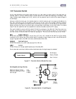
6.3 Connecting a 2-Wire Loop-Powered 4-20mA Sensor 

 
The iRIS 220 /iRIS 320 also supports the connection of many types of industry standard 4-20mA current loop 
instruments such as ultrasonic or radar level sensors.  A very common configuration used with these devices 
is known as two-wire or loop-powered mode. This requires only two wires to the sensor and the 4-20mA loop 
current provides power for the sensor as well as being the proportional Analog sensor signal.   
 
However,  theses  sensors  often  require  a  minimum  voltage  across  them  that  may  not  be  reliably  achieved 
with a 12V supply, taking into account the voltage drop across the sense resistor.  In such cases, a separate 
12-24V boosted sensor supply is recommended.   
 
The  diagram  below  shows  the  recommended  connection  diagram  for  such  an  installation.    It  assumes  the 
use of AI1 as the desired input channel.  
 
The 250

 sense resistor generates a 1-5V signal (from the 4-20mA current), which is then measured at the 

Analog  input.  The  sensor  should  be  configured  for  the  correct  channel,  scaling  and  logging  regime  as 
described  in  section  4.3.8.    An  offset  value  will  be  required  as  part  of  the  configuration,  as  the  4mA  (1V) 
offset needs to be eliminated. 
 
 
TOP 


BOTTOM 
 

iRIS I/O Connector 


  -               + 

External 

12V Battery 

(Required) 


Signal      4-20mA Sensor 

Isolated 
12V – 24V 
DC- DC 
Converter
 

-    + 
24V 


12V 
-    + 

250


Resistor 

Charging source 
 e.g solar panel 

Содержание iRIS 220

Страница 1: ...iRIS 220 iRIS 320 User Guide For Software Version V1 19 Requires Firmware Version V2 19...

Страница 2: ...use of this product All examples and diagrams shown in this manual and any supplied software examples are intended as a guide to understanding this product not to guarantee operation iQuest NZ Ltd acc...

Страница 3: ...tion 12 3 Installation 13 3 1 Removing Replacing the Electronic Assembly iRIS 220 13 3 2 Opening Closing the Housing iRIS 320 iRIS 320V 13 3 3 Removing fitting the SIM card GSM models only 13 3 4 I O...

Страница 4: ...omms Related Screens 48 5 3 SMS Communication 51 5 4 General Hints 52 6 Sensor Connection Examples 53 6 1 Connecting a Flow Meter or Rain Gauge 53 6 2 Connecting a 0 5V Pressure Transducer 54 6 3 Conn...

Страница 5: ...ces 32 Table 4 Supplementary Logging Flag Definitions 33 Table 5 Status LED Indication Modes 41 Figure 1 iRIS 220 5 Figure 2 iRIS 320 iRIS 320V 6 Figure 3 SIM Carrier 13 Figure 4 I O Connector 14 Figu...

Страница 6: ...designation for the particular model e g GPRS or CDMA 1X 1 2 Hardware PCB Revision As from firmware version 2 19 software version 1 19 this manual has been completely updated to refer to the new versi...

Страница 7: ...also the enclosure design The following two sections explain the key differences between the two models 2 2 General Characteristics iRIS 220 The iRIS 220 is supplied in a lightweight extruded alumini...

Страница 8: ...s used to delay the alarm trigger for analog inputs and to determine the time over which pulse input counters should be totalised rainfall etc Three additional sensors 7 9 are reserved for internal me...

Страница 9: ...12V Rechargeable Battery Internal Battery Charger Direct Solar Panel Connection External RF Antenna Connector Keypad LCD iRIS 220 2 4 2 9 2 iRIS 320 2 4 2 9 2 iRIS 320V 2 4 2 9 2 SDI 12 Interface sup...

Страница 10: ...Inputs 30Vdc maximum input switch to 0Vdc to activate Link selectable for either mechanical 20Hz or electronic 5kHz switching 2 x Digital Outputs 1 x Switched 12V out max 300mA 1 x Open drain pull do...

Страница 11: ...ttery Voltage Supply Voltage Internal Temperature C or F Received Signal Strength RSSI SDI 12 Interface SDI 12 hardware interface that fully complies with the SDI 12 electrical standard Software suppo...

Страница 12: ...se this mode 2 8 3 Alternative Wireless Connectivity CSD SMS Two other wireless connection modes other than GPRS CDMA 1X are also possible These are CSD Circuit Switched Data or SMS Short Message Serv...

Страница 13: ...ain information from one of the following data sources Analog Input 1 Analog Input 2 Analog Input 3 Analog Input 4 Pulse Counter attached to Digital Input 1 Pulse Counter attached to Digital Input 2 S...

Страница 14: ...ensation offset for fine control See Section 4 3 14 2 8 9 Security The iRIS 320 can be configured with a PIN code to prevent unauthorised access to restricted information through the LCD and keypad Th...

Страница 15: ...right hand screw completely and put in a safe place Undo the two left hand screws until their heads are just fully clear of the front s face The front should then be able to be swung open to the left...

Страница 16: ...12V 0 8A Hr sealed lead acid battery Upon installation you will need to connect this battery as it is shipped disconnected to preserve battery life It should also be disconnected if the unit is not g...

Страница 17: ...ing semiconductor fuse It can also be used to charge an external battery connected to the GND and 12V terminals In the event that the external battery draws excessive current the charger will enter a...

Страница 18: ...p to 5kHz In this mode the input is normally pulled up to 3 6V through a 57K resistance providing a wetting current of approximately 60 A Figure 6 Digital Input Circuit IMPORTANT NOTE In almost all in...

Страница 19: ...up to 300mA Typically this output will be used to drive a sensor relay or lamp powered by the iRIS 12V supply WARNING Care should be taken to avoid the load discharging the internal and or external 12...

Страница 20: ...0 iRIS 320V antenna is fitted through a compression gland in the bottom of the case Internally the antenna terminates at a female BNC connector on the circuit board In areas of marginal coverage this...

Страница 21: ...unting screws are M4 machine screws or Twinfast wood screws NOTE It is very important that the three M5 Allen Key screws on the front panel are tightened firmly after installation to maintain the IP65...

Страница 22: ...es a terminal emulator that is similar in function to HyperTerminal iLink is available from the iQuest website 4 1 Terminal Connection The iRIS RS232 port is a DTE Data Terminal Equipment configured p...

Страница 23: ...IS Set your terminal properties as shown in the dialog boxes below If you have connected the iRIS to any port other than COM1 make an appropriate selection from the drop down combo box The iRIS RS232...

Страница 24: ...ecause the iRIS does not echo received characters it is necessary to enable Echo typed characters locally otherwise you will not see the characters that you type in at the terminal Also set the Line d...

Страница 25: ...RIS through the RS232 port or UDP socket A you will be presented with the main menu To make a menu selection type a number followed by Enter Invalid menu selections will result in the display of an er...

Страница 26: ...3 Radio only Once the power save mode has been entered you will then be prompted to enter the power source for the charger 0 for fixed dc power supply or 1 for solar This selects the battery charging...

Страница 27: ...System DO address for the device Address Enter a value between 0 and 32767 the factory default is 1 This address is used to identify the unit in all System DO communications NOTE An address of 0 is n...

Страница 28: ...ll appear Wireless module inactive Terminal unavailable Assuming the modem is active the two scenarios are as follows If the internal modem is powered up but a GPRS CDMA 1X or CSD session is not in pr...

Страница 29: ...ters user name and password are configured When this option is selected you will be prompted firstly to enter a user name then a password Many providers do not require any login credentials in which c...

Страница 30: ...uest during initial calibration and setup of the iRIS and uniquely identifies the hardware by manufacturer and serial number L C Location Cell string This is the exact cell identification string as re...

Страница 31: ...hone number Sec Phone No Enter the number of a second cellphone that will also receive iRIS initiated text messages SMS mode or a secondary telephone number of the base station that the iRIS should ca...

Страница 32: ...active Duration sec Enter a value of 0 if you want to maintain a continuous GPRS CDMA 1X session Option 2 When this option is selected you will be prompted to enter the length of time in minutes betwe...

Страница 33: ...l 2 The Sensor Selection menu is where you select the sensor that you want to configure From this menu you can see at a glance which sensors are enabled for logging and if enabled their source and nam...

Страница 34: ...te that analog inputs 3 and 4 will give zero on iRIS units with V1 1 revision hardware Source 0 15 Source Description Raw Range Multiplier Offset Log Multiplier 0 Unused disabled N A N A N A N A 1 Ana...

Страница 35: ...es vector calculations to calculate the average After selecting the mode you will then be prompted to configure the extended datalogging options by entering in a number that represents a set of option...

Страница 36: ...s you will need to enter a logging multiplier of 100 NOTE Care needs to be taken in the selection of an appropriate logging multiplier because the iRIS logs data as signed 16 bit integer values 32768...

Страница 37: ...lection menu Option 1 When this option is selected you will be prompted to enable disable the alarm Enable 0 No 1 Yes Enter a value of 0 to disable the alarm Enter a value of 1 to enable it Option 2 W...

Страница 38: ...ou want to configure From this menu you can see at a glance which outputs are enabled Output Selection 0 Exit 1 Output 1 Enabled 2 Output 2 Disabled Option 0 Select this option to return to the main m...

Страница 39: ...trigger enabled 4 High Trigger Activate when Sensor 1 last logged value trigger setpoint and trigger enabled 5 Force output permanently on Required for both outputs if Unidata high speed encoder used...

Страница 40: ...tured on the hour The final output activation for the day will occur at 23 59 in preparation for the midnight measurement 4 3 14 Date Time Cfg Level 2 The Date Time Cfg menu is where the various time...

Страница 41: ...iguration items Miscellaneous 0 Exit 1 Temperature C 2 Initialize 3 WXT510 No Option 1 This option defines the temperature scale in which the internal iRIS temperature will be displayed and logged Tem...

Страница 42: ...ess is via the cellular modem or via a special PSTN landline adaptor Contact iQuest for details on this feature Mode 0 Cellular 1 Landline Option 2 This list based option enables which sensors will be...

Страница 43: ...dication Modes 5 1 2 Diagnostic LEDs The iRIS has eight internal LED indicators that are useful for diagnostic purposes Please note that these indicators are only active in certain power management mo...

Страница 44: ...ed call in is pending or in progress D Indicates presence of data in transmit buffer Invisible No data in transmit buffer Solid Some data in transmit buffer Padlock Indicates current access level Invi...

Страница 45: ...Status 2 Status 3 Status 4 Main Menu Sensors 1 9 Sensor Menu Sensor Data Totalisers 1 2 Comms Status 3 Full Access PIN code 0 and user is logged in Level 0 Level 1 Level 2 Level 3 Level 4 Level 5 Leve...

Страница 46: ...creens Use the or keys to switch the logging on or off Pressing the Enter key will return the display to the top level Welcome System Status 1 screen System Status 1 Screen Level 1 The System Status 1...

Страница 47: ...This screen provides an overview of each sensor Line 1 indicates sensor ID data source and its composite status including if sensor is enabled if sensor and alarm s are enabled if sensor and alarm s a...

Страница 48: ...hows the trigger and reset levels used to generate an alarm and the duration used to qualify the alarm If the sensor gets its data from an Analog input the duration is used to provide an alarm delay I...

Страница 49: ...the top sample is displayed on the top right hand side 5 2 7 Totaliser Related Screens The Totaliser screens show yesterday s total the daily since 00 00 00 today and running totals for the two pulse...

Страница 50: ...s less than 6 Comms Menu Screen Level 4 The comms menu screen is used to select communication options Comms Setting Screen 1 8 Protocol Level 5 The GPRS CDMA 1X Protocol screen displays the station ad...

Страница 51: ...munication with a base station E g HydroTel 2000 Comms Setting Screen 5 8 Schedule 1 Level 5 This screen displays the time range during which the unit is allowed to make a connection to the GPRS CDMA...

Страница 52: ...l driver code included a user script then the RS232 port can be used to communicate with an external device such as an intelligent sensor In this situation the user script will typically store the ret...

Страница 53: ...sor number name and current value of all the enabled sensors The format is best shown in this example My Site Name 1 Water Lvl 27 69 2 Batt Volts 12 73 3 Supp Volts 23 90 If the message was sent becau...

Страница 54: ...event it becoming discharged Always check the time and date when commissioning the unit Immediately following installation use the initialisation function available on the Miscellaneous terminal menu...

Страница 55: ...p the input debounce mode Both inputs can be used simultaneously and each input has three associated totalisers which are viewable from the LCD See section 5 2 7 These totalisers operate even if the i...

Страница 56: ...ows the connection of a transistor switch module with control from DO1 TOP BOTTOM iRIS I O Connector The sensor should be configured for the correct channel scaling and logging regime as described in...

Страница 57: ...s them that may not be reliably achieved with a 12V supply taking into account the voltage drop across the sense resistor In such cases a separate 12 24V boosted sensor supply is recommended The diagr...

Страница 58: ...utput generates a pulse for each increment and the other for each decrement in level The iRIS maintains a record of these steps and therefore the relative level These instruments normally require a 12...

Страница 59: ...s is readily obtained from the iRIS A supplementary 12V battery can be connected if desired Typically this type of instrument requires very little current so the internal iRIS 320 battery will normall...

Страница 60: ...ng the SDI 12 terminal mode to access SDI 12 instruments directly Also refer to Appendix C SDI 12 iRIS 320 320V only for detail on the SDI 12 specification NOTE The original PCB revision 1 1 iRIS 320...

Страница 61: ...rements are logged as a secondary sensor linked to rainfall which must be configured as sensor 6 Hail is logged with an array ID of 10 and it shares the same logging configuration as rainfall logging...

Страница 62: ...in resistance caused by the internal input impedance of the iRIS input channel to take into account see Section 3 4 4 Analogue Inputs Therefore the voltage measured by the iRIS for a given water level...

Страница 63: ...defined IP address and port number are non zero If Socket A is not used set it to the same values as Socket B See Appendix F for a list of the network settings for the iQuest APN or iQuest Global Data...

Страница 64: ...iRIS 220 iRIS 320 V1 19 User Guide 62 62 iQuest NZ Ltd PO Box 15169 Hamilton New Zealand Tel 64 7 857 0810 Fax 64 7 857 0811 Email iquest iquest co nz 9 User Notes...

Страница 65: ...used In all cases the DSR line from the modem or radio is used to enable the RS232 port and the RI line sets the data rate to a fixed rate normally 1200 bps Figure 13 Typical RS232 Data Radio Cable Fi...

Страница 66: ...12 Partition 0 This partition holds the standard sound files for the digits 0 9 a decimal point and minus These are used to create the reported measurement values This partition should be loaded with...

Страница 67: ...s however is possible Some SDI 12 users connect more than ten sensors to a single data recorder Multi parameter means that a single sensor may return more than one measurement For example some water q...

Страница 68: ...be greater than 1 5 volts per microsecond Ground Line The ground line must be connected to the circuit ground and the earth ground at the data recorder The sensor circuit ground also must be connecte...

Страница 69: ...tion is shown in the diagram below TOP AI2 Analog Input 2 AI1 Analog Input 1 AGND Analog Common Ground DI2 Digital Input 2 DI1 Digital Input 1 DO2 Digital Output 2 DO1 Digital Output 1 DGND Digital Co...

Страница 70: ...V1 1 PCB 13 4 Diagnostic LEDs The iRIS has several internal LED indicators that are useful for diagnostic purposes Please note that these indicators are only active in certain power management modes...

Страница 71: ...enclosure of an iRIS 320 It has three wires two of which are terminated with a bootlace ferrule for insertion into the iRIS I O connector The third output wire has a screw terminal to attach the trans...

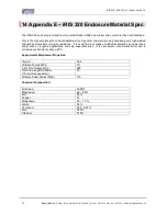
Страница 72: ...ossessing very high welded strength and excellent corrosion resistance It is used for many types of welded assemblies such as tanks dump trucks cryogenic applications and ship superstructures It is no...

Страница 73: ...ings for iQuest APN or iQuest Global Data Network iQuest APN APN iquest co nz iQuest Host IP Address 192 168 1 10 Default Binary Port 7777 Default ASCII Port 7778 iQuest Global Data Network Network St...

Отзывы: