

Bedienungsanleitung Verstärker
Operating Instructions Amplifier
OV580510, OV580515, OV580530, OV580910, OV580915, OV580930, OV584510,
OV584515, OV584530, OV584910, OV584911, OV584915, OV584930
Einleitung
Verstärker werden als Bestandteil eines übergeordneten Gesamtsystems zur Er-
fassung von Objekten eingesetzt. Sie können nur mit einem Sender OS... und ei-
nem Empfänger OE... betrieben werden.
Introduction
Amplifiers are used as the components of a higher-level overall system for the
detection of objects. They can only operate with one Transmitter OS... and one
Receiver OE...
Arbeitsweise
Die Geräte dieser Serie sind 1-Kanal-Automatik-Verstärker bei denen kein Einstel-
len oder Nachstellen erforderlich ist. Sie erkennen beim Einschalten den Montage-
abstand, pegeln sich sekundenschnell optimal ein und regeln auf das System ein-
wirkende Störeinflüsse permanent und zu 100 % aus.
Der Verstärker arbeitet mit moduliertem Infrarotlicht, wodurch eine hohe Sicherheit
gegen Fremdlicht erreicht wird. Die Schaltung ist so ausgelegt, daß nur Signale
richtiger Frequenz und Phasenlage erkannt werden. Dadurch ist eine Beeinflus-
sung durch andere Lichtschranken nahezu ausgeschlossen.
Montage
Die Verstärker sind für eine schnelle Montage und Demontage konzipiert und besit-
zen daher einen Steckanschluß. Um eine sichere Funktion zu garantieren und eine
Beschädigung des Gerätes zu vermeiden immer einen Stecksockel benutzen.
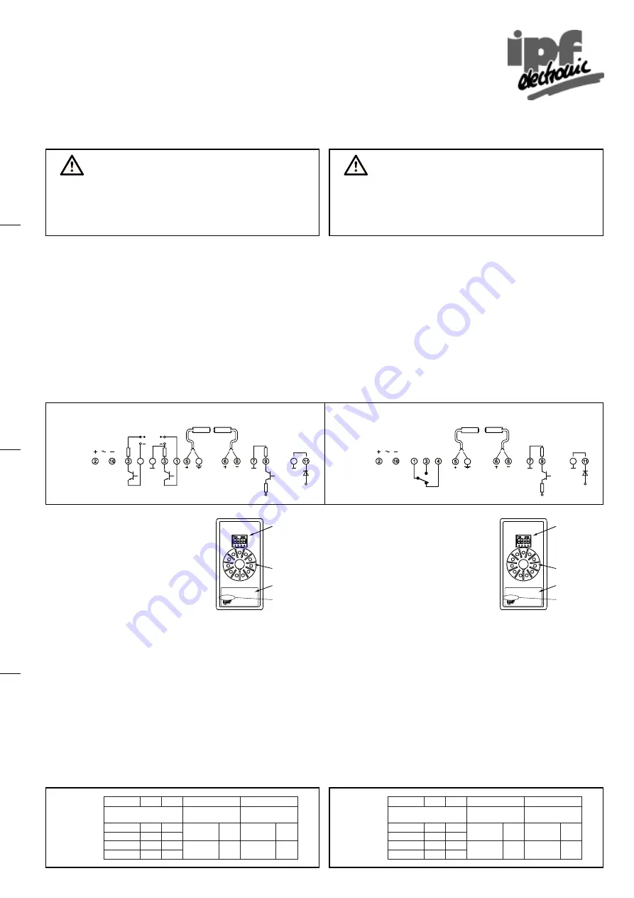
Anschlußschema
Principle of operation
The devices of this series are 1-channel automatic amplifiers, which need no
adjustments. After switching on the voltage supply, the eyes detect the range between
them and adjust the transmit power to the optimum level.
The amplifier works with modulated infrared light which provides high immunity to
ambient light. The electronic circuits are designed to detect only those signals with
the correct frequency and phase relation. This almost completely excludes
interference from other light barriers.
Installation
The device includes a plug for simple installation. As a safe operating procedure
and to avoid damaging the device, use an 11-PIN socket.
Wiring diagram
Betriebsspannung
Die Betriebsspannungsangabe ist in der Geräte-
beschreibung enthalten. Die Gerätebeschreibung
ist auf dem rückseitigen Typenschild.
Funktionen
Die Funktionen sind mit dem DIP-Schalter auf der
Geräterückseite einzustellen.
- Schaltfunktion
Die Schaltfunktion beschreibt das Verhalten des Schaltausganges beim Unterbre-
chen des Infrarotstrahls. Bei Dunkelschaltung erfolgt bei unterbrochener Lichtstrecke
ein Ausgangssignal. In Hellschaltung erfolgt bei freier Lichtstrecke ein Ausgangssignal
- Sendefrequenz
Bei der Montage mehrerer Sensoren dicht nebeneinander, ist ein Betrieb der Ver-
stärker bei verschiedenen Sendefrequenzen noch möglich. Jeder Verstärker wertet
nur das Signal mit der eigenen Sendefrequenz aus.
- Grundleistung
Die Grundleistung gibt an, wie der Verstärker die Leistung regelt.
Low1: Der Sendestrom wird auf den optimalen Wert für die Strecke eingestellt (emp-
findlichste Einstellung).
Low2: Wie Low1, aber der Verstärker ist unempfindlicher (benötigt eine höhere
Streckendämpfung, um eine Änderung am Schaltausgang zu erzeugen).
High1:Der Sendestrom beträgt mindestens 50 % des Maximalwertes.
High2:Der Sendestrom beträgt mindestens 90 % des Maximalwertes.
DIP-Schaltereinstellung
Supply voltage
The supply voltage is specified in the device
description. On the bottom of the amplifier is the
type plate with the device description.
Function
The functions are selectable by DIP-switches on
the bottom of the amplifier.
- Switching mode
The switching mode determines the output behavior upon interruption of the infrared
beam. When the amplifier is set to dark mode, there is a output signal as long as the
beam is broken. In light mode, there is an output signal when the beam is present.
- Transmit frequency
The transmit frequency means the modulation frequency at which the amplifier works.
If more than one sensor head is mounted side by side, the amplifier must be set to
different frequencies.
- Basic transmit level
The basic transmit level is the minimum transmit power level on an infrared amplifier
Low1: The transmit power level is always set to the optimal value for constant high
switching sensitivity.
Low2: The amplifier works like low1 basic transmit level but the device is less sen-
sitive.
High1:The transmit power is always at least 50 % of the maximum power level.
High2:The transmit power is always at least 90 % of the maximum power level.
DIP switch setting
230VAC, Relais, alarm, auto
OV 58 49 10
sensor opt, verstärker
Tel. 0 23 51 / 93 65-0
Typenschild
Stecker
DIP-Schalter
Betriebsspannung
zum Beispiel: 230VAC
230VAC, Relais, alarm, auto
OV 58 49 10
sensor opt, verstärker
Tel. 0 23 51 / 93 65-0
Type plate
Plug
DIP-switch
Supply voltage
for example: 230VAC
Sicherheitshinweise
Der Einsatz von Infrarot-Verstärkern OV58... ist nicht zulässig für Anwendungen,
bei denen die Sicherheit von Personen von der Gerätefunktion abhängig ist.
Der Betreiber des übergeordneten Systems, z.B. einer Maschinenanlage,
ist für die Einhaltung der nationalen und internationalen Sicherheits- und
Unfallverhütungsvorschriften verantwortlich.
Safety instructions
The operation of infrared amplifier OV58... is not authorized for applications
where the safety of a person depends on the function of the device.
The operator of the higher-level overall system, e.g. a machine installation,
is responsible for complying with the national and international safety and
accident prevention regulations which apply to the specific use.
Test-Eingang
Test input
7
offen/open = inaktiv/inactive
0 V
= aktiv/active
NO
NC
COM
Relais
Relay
Betriebsspannung
Supply voltage
Empfänger
Receiver
Gelb/
Yellow
Schirm/
Shield
7
Ground
Sender
Transmitter
Rot/
Red
Schwarz/
Black
NPN
(max. 30 VDC)
PNP
Transistorausgang
Transistor output
7
7
Betriebsspannung
Supply voltage
Empfänger
Receiver
Gelb/
Yellow
Schirm/
Shield
7
Ground
Sender
Transmitter
Rot/
Red
Schwarz/
Black
Test-Eingang
Test input
7
offen/open = inaktiv/inactive
0 V
= aktiv/active
OV580510
OV580515
OV580530
OV584510
OV584515
OV584530
Alarmausgang
Alarm output
24 VDC
pnp
Alarmausgang
Alarm output
24 VDC
pnp
OV580910
OV580915
OV580930
OV584910
OV584911
OV584915
OV584930
1
2
3
4
/
g
n
u
t
s
i
e
l
d
n
u
r
G
r
e
w
o
p
ti
m
s
n
a
rt
c
i
s
a
B
/
n
o
it
k
n
u
ft
l
a
h
c
S
e
d
o
m
g
n
i
h
c
ti
w
S
/
z
n
e
u
q
e
rf
e
d
n
e
S
z
n
e
u
q
e
rf
ti
m
s
n
a
r
T
2
h
g
i
H
N
O
N
O
l
e
k
n
u
d
N
O
z
H
k
1
,
4
N
O
1
h
g
i
H
N
O
F
F
O
2
w
o
L
F
F
O
N
O
ll
e
h
F
F
O
z
H
k
7
,
3
F
F
O
1
w
o
L
F
F
O
F
F
O
1
2
3
4
/
tr
a
s
b
e
ir
t
e
B
e
d
o
m
n
o
it
a
r
e
p
O
/
n
o
it
k
n
u
ft
l
a
h
c
S
e
d
o
m
g
n
i
h
c
ti
w
S
/
z
n
e
u
q
e
rf
e
d
n
e
S
z
n
e
u
q
e
rf
ti
m
s
n
a
r
T
2
h
c
a
e
T
N
O
N
O
l
e
k
n
u
d
k
r
a
d
N
O
z
H
k
1
,
4
N
O
1
h
c
a
e
T
N
O
F
F
O
2
w
o
L
F
F
O
N
O
ll
e
h
t
h
g
il
F
F
O
z
H
k
7
,
3
F
F
O
1
w
o
L
F
F
O
F
F
O
OV580510
OV580515
OV584510
OV584515
OV580910
OV580915
OV584910
OV584911
OV584915
OV580530
OV580930
OV584530
OV584930