A
C
B
TAPE
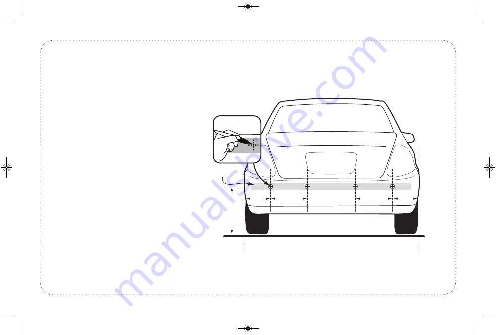
SENSOR INSTALLATION
(Continued)
DIRECT ON VEHICLE BUMPER
page 7
iPark_IPTSWR400_Manual_Layout 1 10/30/14 9:27 AM Page 7
Страница 1: ...IPTSWR400 WIRELESS PARKING ASSIST SYSTEM MANUAL iPark_IPTSWR400_Manual_Layout 1 10 30 14 9 27 AM Page 1...
Страница 2: ...n Sensor Maintenance 4 Audible Buzzer Function 5 Packing List Installation Tools 6 7 Sensor Installation 8 Wiring Diagram 9 ECU Installation 10 Troubleshooting 11 Function Test After Installation 12 V...
Страница 3: ...hile parking The manu facturer its distributors and sales agents do not guarantee against or assume liability for collisions or damages while reversing your vehicle ABOUT THE PRODUCT This Parking Assi...
Страница 4: ...can be used on both metal bumpers and plastic bumper covers Precise detection range Self Test and Auto Anti Falsing Alert technology TECHNICAL SPECIFICATIONS Rated Voltage 12V DC Power Consumption 3 6...
Страница 5: ...e ultrasonic signal Soft fabrics carpeting or padded sur faces may absorb the ultrasound and not give an accurate reading Buildings with staggered walls or insets may also absorb or deflect the signal...
Страница 6: ...ve VOICE alerts for distance in FEET On Screen display of object location and distance in FEET page 4 SENSOR STATUS VOICE STATUS Siren Icon Crossed The unit beeps no voice alert Siren Icon Not crossed...
Страница 7: ...Mounting Tape 1 Manual INSTALLATION TOOLS Power Drill Tape Measure Electrical Tape Scissors Soldering Iron Solder Hole File Screw Driver Skill Knife Approximately 30 to 60 Minutes page 5 IMPORTANT The...
Страница 8: ...18 to 25 inches Position the 4 sensors to be equally spaced apart on the bumper Best location is outer two sensors spaced 8 to 10 inches in from outer edge of vehicle Measure the distance between the...
Страница 9: ...A C B B A TAPE SENSOR INSTALLATION Continued DIRECT ON VEHICLE BUMPER page 7 iPark_IPTSWR400_Manual_Layout 1 10 30 14 9 27 AM Page 7...
Страница 10: ...UMPERS SENSOR B SENSOR C SENSOR D REVERSE LIGHT WIRING DIAGRAM Reverse Light 12V DC Red Black Ground Sensors ABCD Wiring Diagram for 4 Sensor Rear System page 8 DISPLAY Ignition 12V DC Red Chassis Gnd...
Страница 11: ...Pull Back 12V Lens Cover Module ECU INSTALLATION Reverse Light 12V Red Ground Black page 9 iPark_IPTSWR400_Manual_Layout 1 10 30 14 9 27 AM Page 9...
Страница 12: ...ensor assembly Clean sensor to clear false warning or range too short False warning or range to short Trouble Solution A Sensors are angled down seeing ground surface Adjust with angle ring B Sensor h...
Страница 13: ...N Function test is performed by holding a wooden board 12 x 36 upright behind the vehicle and slowly backing the car to test each of the sensors are functioning correctly page 11 iPark_IPTSWR400_Manua...
Страница 14: ...E function is ON the siren symbol is clear If the VOICE function is OFF the siren symbol is crossed out page 12 DISPLAY BUTTON FUNCTIONS VOLUME REST DEFAULT IS 7 PRESS FOR 3 SECONDS VOLUME VOLUME VOIC...
Страница 15: ...e will Increase from SOFT to LOUD There are a total of 13 steps to the volume level VOLUME RESET FUNCTION Press and HOLD the Key for 3 Seconds The Volume will reset to Level 7 page 13 VOLUME LEVEL ONE...
Страница 16: ...installation specialist Please retain your purchase receipt for proof of purchase date and warranty coverage If you purchased this product through a new car dealership you may be entitled to addi tion...