


14
LEGEND
N 728
WIRING DIAGRAM AND LEGEND
WIRING DIAGRAM
SEE APPENDIX
SE 3289 mod els 25/30/35
Control
230V 50Hz +/- 10%
SE 3288 models 25/30/35
Power Tri
400V+N 50Hz +/- 10%
SE 3312 models 40/50/60
Control
230V 50Hz +/- 10%
SE 3313 models 40/50/60
Power Tri
400V+N 50Hz +/- 10%
POWER SUPPLY
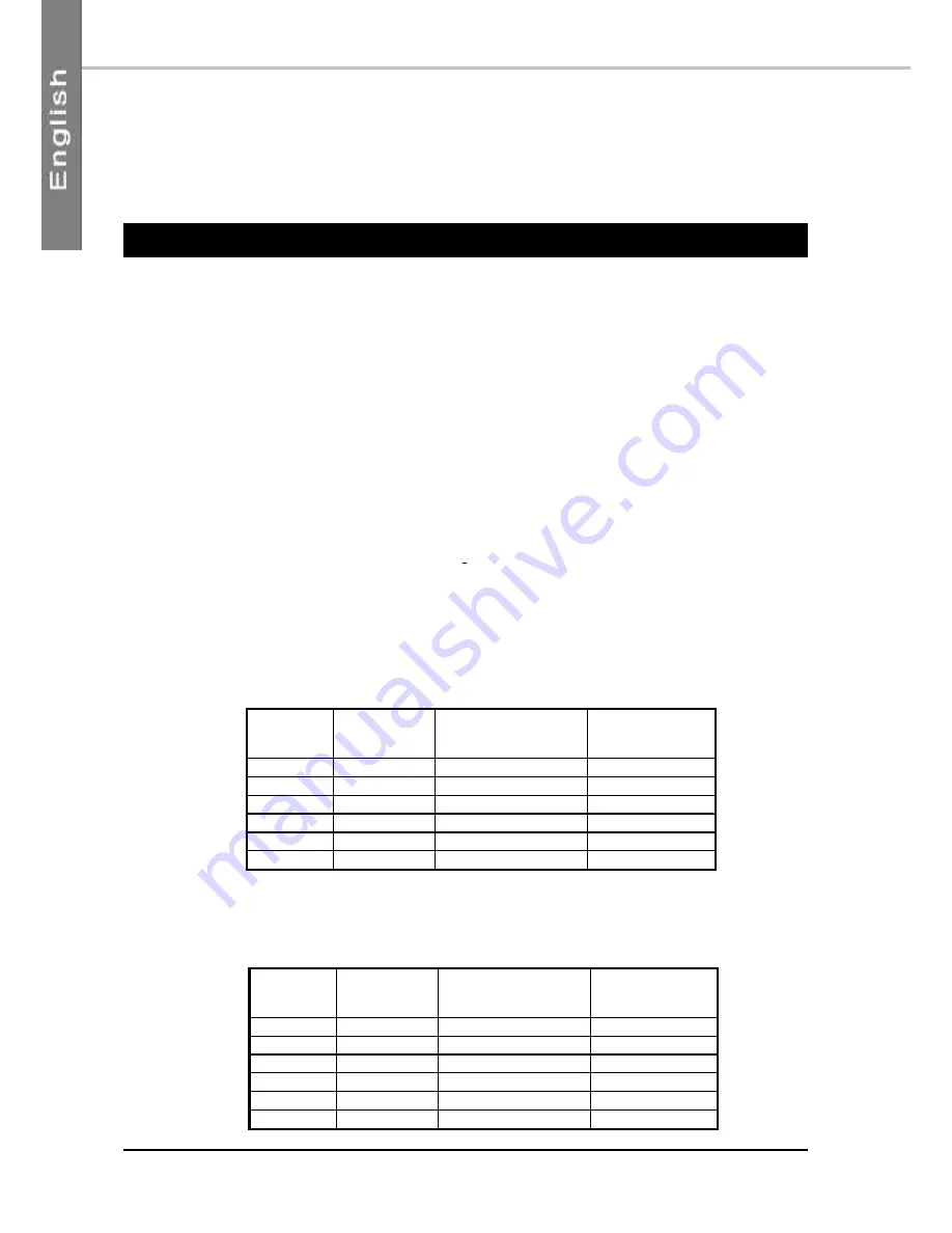
This supply is protected upstream by an FFG general supply fuse holder, to be provided by the installer, in accordance
with Table 1 – Small equipment or Table 2 – Large Equipment. The fuse holder shall be mounted close to the unit.
The electrical installation and the wiring of this unit shall comply with local electrical installation standards.
➢
Thee phase 400 V~ + N Ground:
On terminals P-E ; N ; L1 ; L2 ; L3 on Main Terminal Block X1.
➢
Three phase 400V ~ + Ground: (Models 40 to 80 only: Transformer option obligatory)
On terminals P-E ; L1 ; L2 ; L3 and Ground on Main Terminal Block X1.
25
32 A
25 A
80 A
30
32 A
27 A
82 A
35
40 A
31 A
122 A
40
50 A
44 A
140 A
50
50 A
46.8 A
186 A
60
63 A
53 A
232 A
AQCL
AQCH
FFG Fuse
aM Type
Full load current
(max.) 400V
Starting
amperage (max.)
25
32 A
27 A
82 A
30
32 A
29 A
92 A
35
40 A
33 A
124 A
40
63 A
47 A
142 A
50
63 A
51 A
188 A
60
63 A
56 A
236 A
AQCL
AQCH
FFG Fuse
aM Type
Full load current
(max.) 400V
Starting
amperage (max.)
TABLE 1: CASE SMALL EQUIPMENT
TABLE 2: CASE LARGE EQUIPMENT


