FWB-IDE01A
Overview
3). Mobile Rack Installation Guide:
Fig. 3
Fig. 2
P U S H
6
1
3
2
5
4
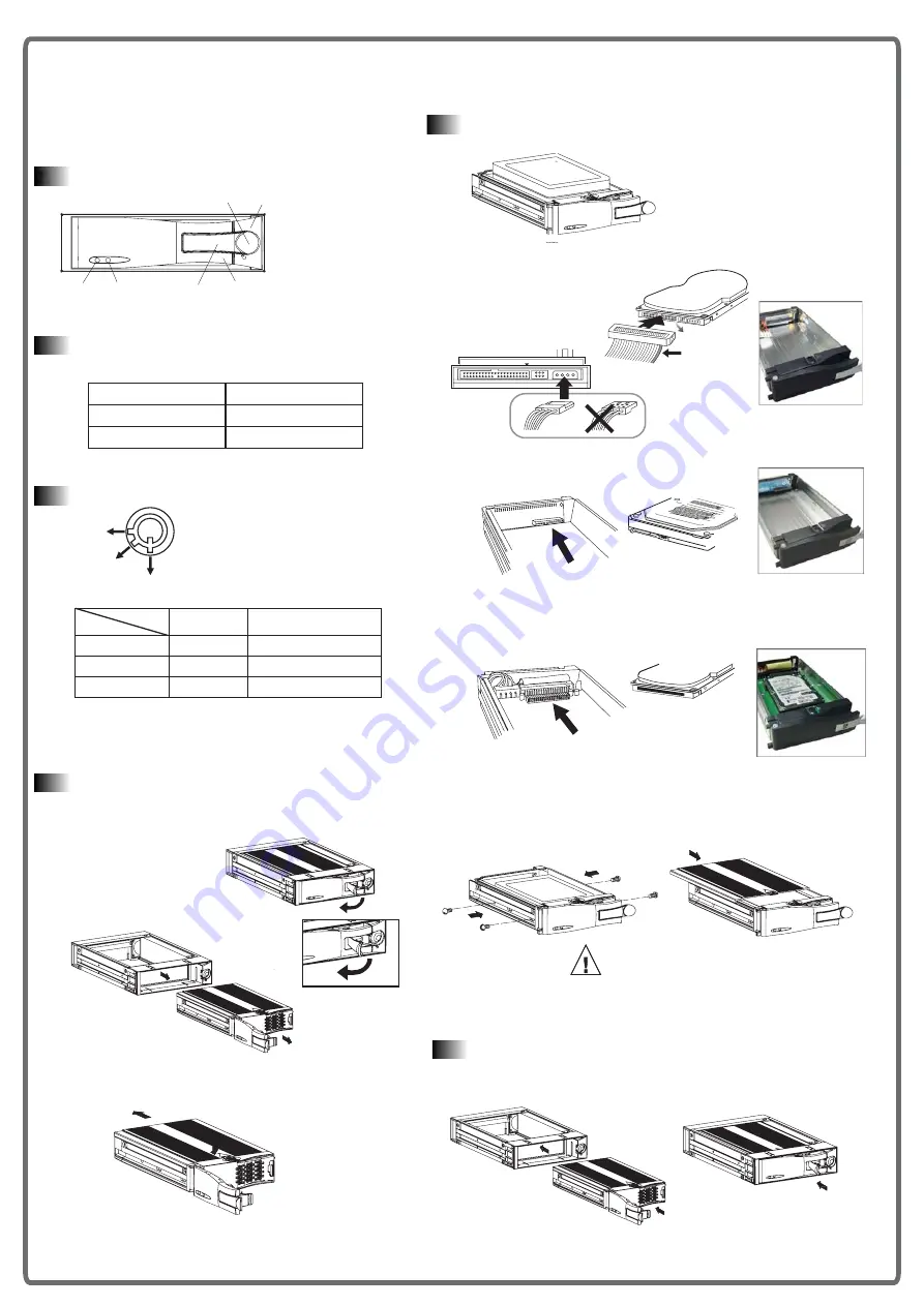
1. HDD Access indicator
2. Power indicator
3. Active-handle
4. Handle
5. Cartridge frame
6. Key lock
1.
Front Panel Description
Key lock
A
B
C
Power status
Status
Segment
Security status
ON
A
Locked (Irremovable)
OFF
B
OFF
C
Locked (Irremovable)
Unlocked (Removable)
3.
Fig. 1
Item
Indicator
Power Indicator
Green LED
HDD Access Indicator
Amber LED
Power Indicator and HDD
Access Indicator
2.
When power is turned on, the indicators display.
Pull the active-handle outward.
1.
Slide the carrier body backin the cartidge frame
3.
Provide three kinds of HDD Mobile Tray for different application.
2.
1-1. Pull the active-handle outward. (Fig.1)
1-2. Pull the handle outward to remove the carrier body away from the
cartridge frame. (Fig.2)
1-3. Push and hold on to release latch, then slide the top
and remove. (Fig.3)
2-1-1. Connect the 3.5" ATA HDD by using IDE-ATAMT01.
2-1-2. Connect the 3.5" SATA HDD by using IDE-SATAMT01.
2-1-3. Connect the 2.5" ATA HDD by using 35-25MT01.
Fig. 7
Fig. 8
3-1. Slide the carrier body back in the cartridge frame. (Fig.7)
3-2. Push the carrier body further into the cartridge frame until fully
inserted. (Fig. 8)
Fig. 5
Fig. 6
Screw driver is not included.
Proper type of screw driver needed!
Caution
2-2. Place the HDD inside carrier body, Use four of the screws provided
to secure theHDD. (Fig.5)
2-3. Place the top cover back to the carrier body by sliding forward to
secure. (Fig.6)
Mobile Rack Introdcution
Installing Hard Disk Drive
(With IDE-SATAMT01)
(With IDE-ATAMT01)
(With 35-25MT01)
3.5" SATA HDD
2.5" ATA HDD
INTERFACE CONNECTOR
IDE
DC INPUT
+5V GND +12V
3.5" ATA HDD
Colored stripe
Pin 1


