3
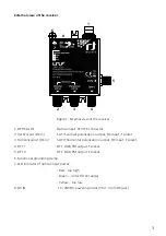
External view of the receiver
1
2
3
4
5
8
7
6
Figure 1. External view of the receiver
1. OPTICAL IN
Optical input. FC/UPC connector.
2. Vertical out (DC in)
SAT IF vertical polarization output, DC input. F socket.
3. Horizontal out (DC in)
SAT IF horizontal polarization output, DC input. F socket.
4. DTT 1
DTT, DAB, FM output. F socket.
5. DTT 2
DTT, DAB, FM output. F socket.
6. Functional grounding clamp
7. LED indicator of optical input power:
- Red – too high
- Green – correct (OLC range)
- Yellow – too low
8. DC IN
10 - 20V DC powering input (3.5/1.3 mm DC jack)


